Method and apparatus for suppression of the airwave in subsea exploration

a technology for subsea exploration and airwave suppression, which is applied in the direction of acoustic wave reradiation, measurement devices, instruments, etc., can solve the problems of reducing the sensitivity of csem data to resistive reservoirs, poor evaluation or non-detection of reservoirs, and te-mode remains largely insensitive to resistive thin layers. , to achieve the effect of less efficient, less airwave, and logistically easy

Inactive Publication Date: 2014-07-10
ZINGER BENTSION
View PDF11 Cites 3 Cited by
  • Summary
  • Abstract
  • Description
  • Claims
  • Application Information

AI Technical Summary

Benefits of technology

[0037]It is the purpose of this invention to suggest a transmitter, which induces the electromagnetic field with a greatly diminished airwave, the procedure for the transmitter tuning up, and the use of the transmitter for surveying the subsea formation. An alternative approach, which is somewhat less efficient but logistically easier, may be implementing by processing two independent sets of data acquired for the same or close transmitter and receiver positions but with different types of transmitters.
[0038]The first aspect of the inven...

Problems solved by technology

On the other hand, the TE-mode remains largely insensitive to resistive thin layers, even if they are practically non-conductive.
Thus, the airwave reduces sensitivity of the CSEM data...

Method used


Image

  • Method and apparatus for suppression of the airwave in subsea exploration
  • Method and apparatus for suppression of the airwave in subsea exploration
  • Method and apparatus for suppression of the airwave in subsea exploration

Examples


Embodiment Construction

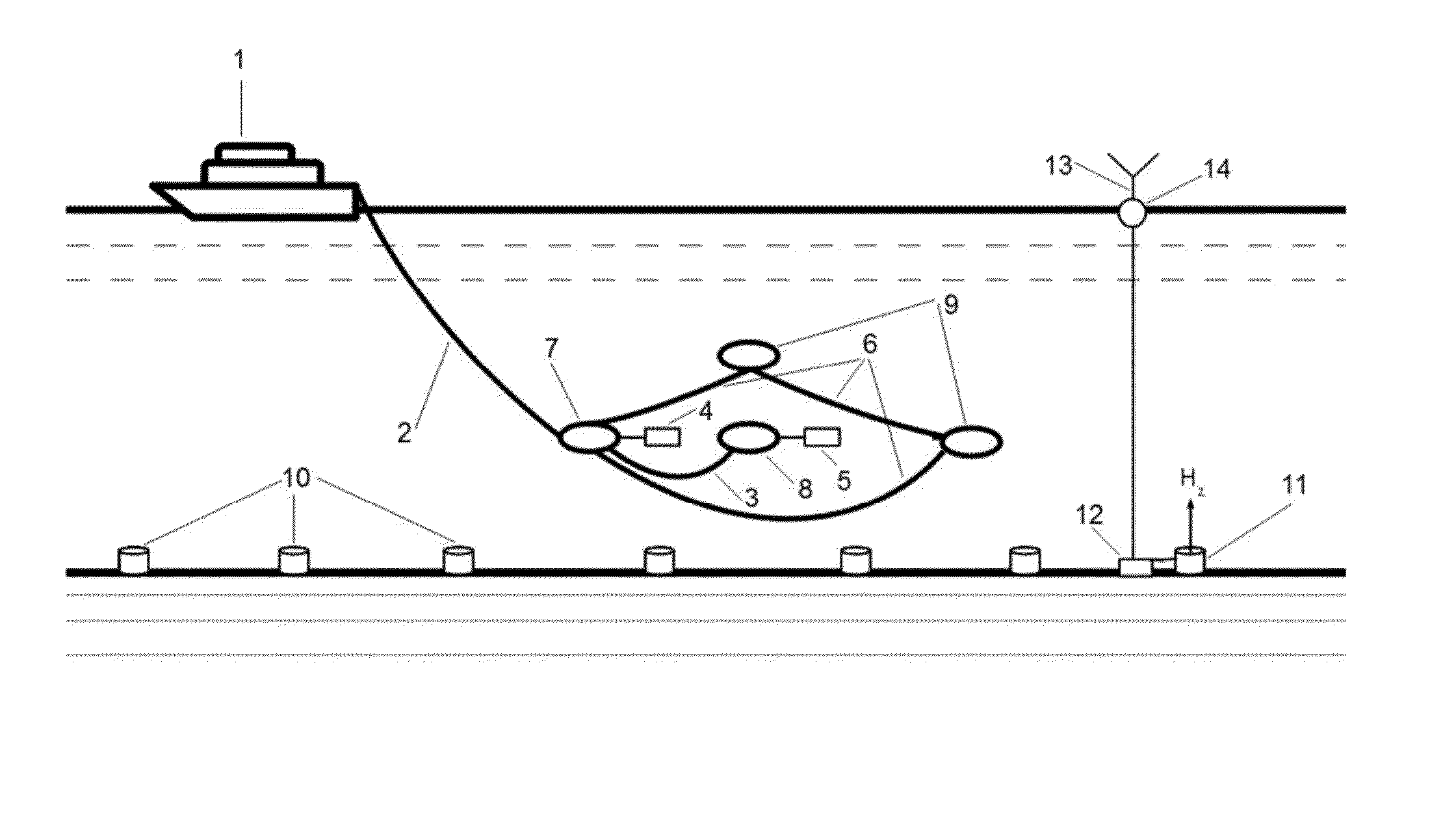
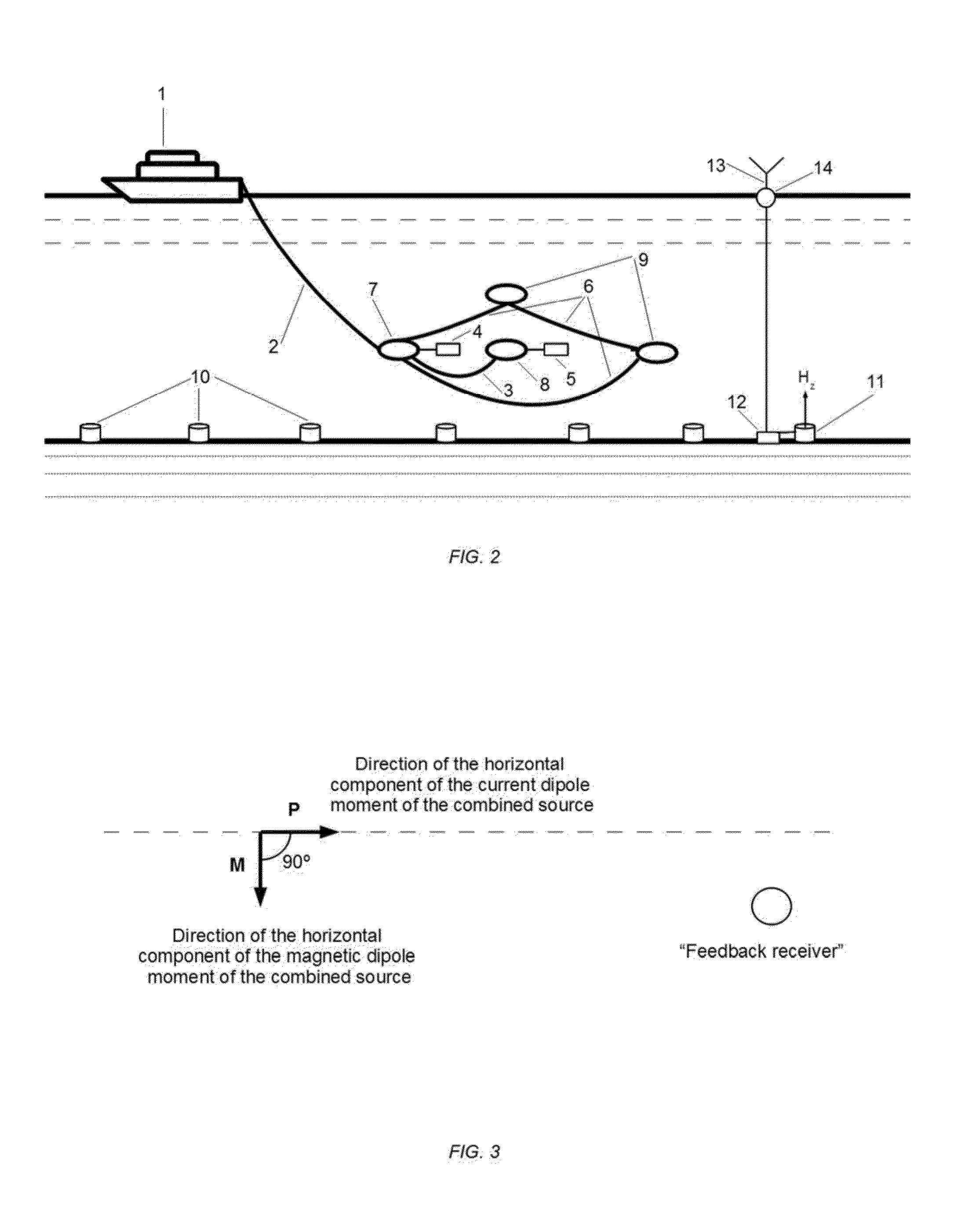
[0054]The electromagnetic fields induced in a stratified medium by a horizontal electric dipole (HED) bears significant similarities to the field induced by a horizontal magnetic dipole (HMD). At large offsets the TE-mode of the field induced by a HED decays in accordance with the same geometrical law as that of the field induced by a HMD. Therefore, a transmitter, which combines electric and magnetic dipole types of the sources, may induce an electromagnetic field with a significantly reduced TE-mode provided the corresponding current and magnetic dipole moments are properly oriented and tuned up. Such tuning up also reduces the airwave without suppressing the TM-pan of the induced field, which is sensitive to thin resistive layers present in the formation. The vertical component of the magnetic field may be used to control the level of the airwave suppression because the vertical component of the magnetic field, like the airwave, is contributed only by the TE-mode. For simplicity,...


PUM


Abstract

The far zone “airwave” that arises when surveying subsea formations is greatly diminished by deployment of the transmitter combining mutually orthogonal horizontal electric and magnetic dipoles with the electric and magnetic dipole moments being locked in a special relationship. At each of the operating frequencies, the amplitude and phase characteristics of the transmitter electric and magnetic dipole moments are determined either from a supplementary measurement earned out using natural and/or controlled field sources, or by minimization of the vertical magnetic field at a remote receiver. Similar results can be obtained when data acquired in two independent surveys—one with the horizontal electric dipole transmitter pointing in one direction and another with a horizontal magnetic dipole transmitter pointing in the orthogonal direction and towed over the same or close positions—are linearly combined to minimize the vertical component of the combined magnetic field at remote receivers.

Description

OTHER PUBLICATIONS [0001]References CitedU.S. PATENT DOCUMENTS3,052,836 ASeptember 1962Postma4,047,098 ASeptember 1977Duroux4,078,510 AMarch 1978Morgan4,617,518 AOctober 1986Srnka4633,182 ADecember 1986Dzwinel4,862,089 AAugust 1989Sigal5,825,188 AOctober 1998Montgomery et al.6,236,211 B1May 2001Wynn6,696,839 B2February 2004Ellingsrud et al.6,717,411 B2April 2004Ellingsrud et al.6,859,038 B2February 2005Ellingstud et al.7,002,350 B1February 2006Barringer0,038,570 A1February 2006Constable7,109,712 B2September 2006Constable0,186,889 A1August 2006Andreis7,529,627 B2May 2009Lisitsyn et al.7,884,612 B2November 2011Conti et al.FOREIGN PATENT DOCUMENTSEP1309887March 2004EP1256019June 2004GB2070345September 1981GB2385923September 2003GB2390904January 2004GB2404444February 2005WO014906February 2002WO100467December 2003WO104844December 2003WO109338April 2004WO081016February 2005WO010560February 2005WO052145May 2006[0002]Amundsen, L., L. et al., Decomposition of Electromagnetic Fields into Upgo...

Claims


Application Information

Patent Timeline
IPC IPC(8): G01V3/12
CPCG01V3/12G01V3/083G01V2003/084
Inventor ZINGER, BENTSION
Owner ZINGER BENTSION
Why Eureka
Try Eureka