Integrated measuring apparatus for measuring vapor pressure and liquid level of liquid tank

a technology of liquid tank and measuring apparatus, which is applied in the direction of pressure difference measurement between multiple valves, instruments, machines/engines, etc., can solve the problems of high cost of above-described sensors with double structures, physical limitations and difficulties in sensor installation, and achieve a high degree of freedom in design

Inactive Publication Date: 2014-07-17
AUTO IND
View PDF0 Cites 11 Cited by
  • Summary
  • Abstract
  • Description
  • Claims
  • Application Information

AI Technical Summary

Benefits of technology

[0008]In addition, the following description relates to an integrated measu...

Problems solved by technology

However the practical implementation of this method is not likely to be feasible because of the use of costly pressure sensor.
However, the above-described sensor with a double structure is expensive and due to...

Method used


Image

  • Integrated measuring apparatus for measuring vapor pressure and liquid level of liquid tank
  • Integrated measuring apparatus for measuring vapor pressure and liquid level of liquid tank
  • Integrated measuring apparatus for measuring vapor pressure and liquid level of liquid tank

Examples


Embodiment Construction

[0022]The following description is provided to assist the reader in gaining a comprehensive understanding of the methods, apparatuses, and / or systems described herein. Accordingly, various changes, modifications, and equivalents of the methods, apparatuses, and / or systems described herein will be suggested to those of ordinary skill in the art. Also, descriptions of well-known functions and constructions may be omitted for increased clarity and conciseness.

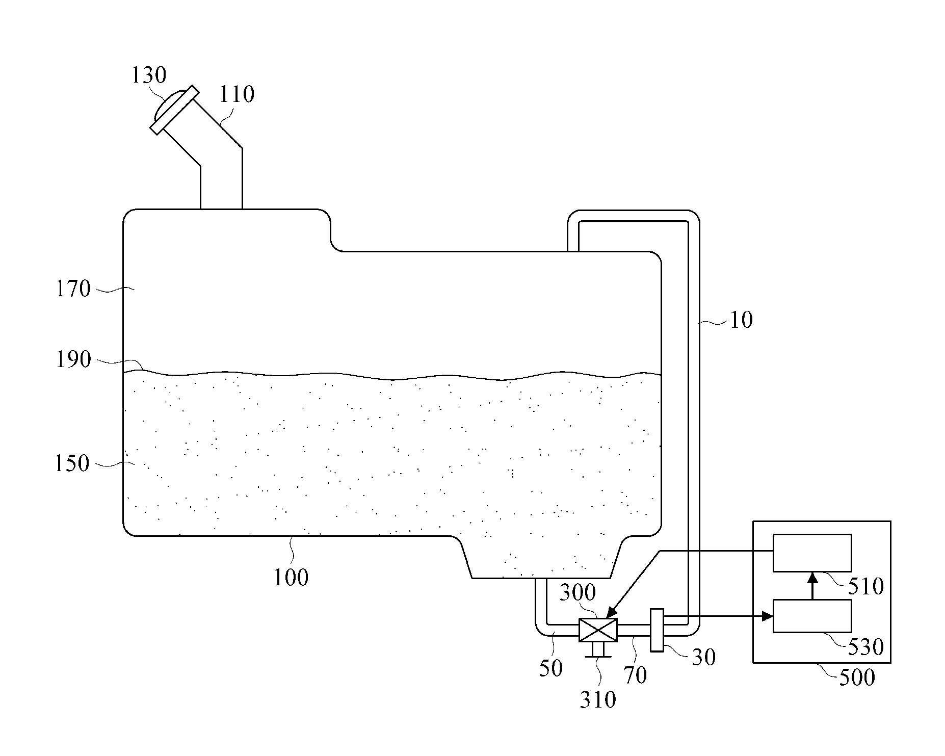
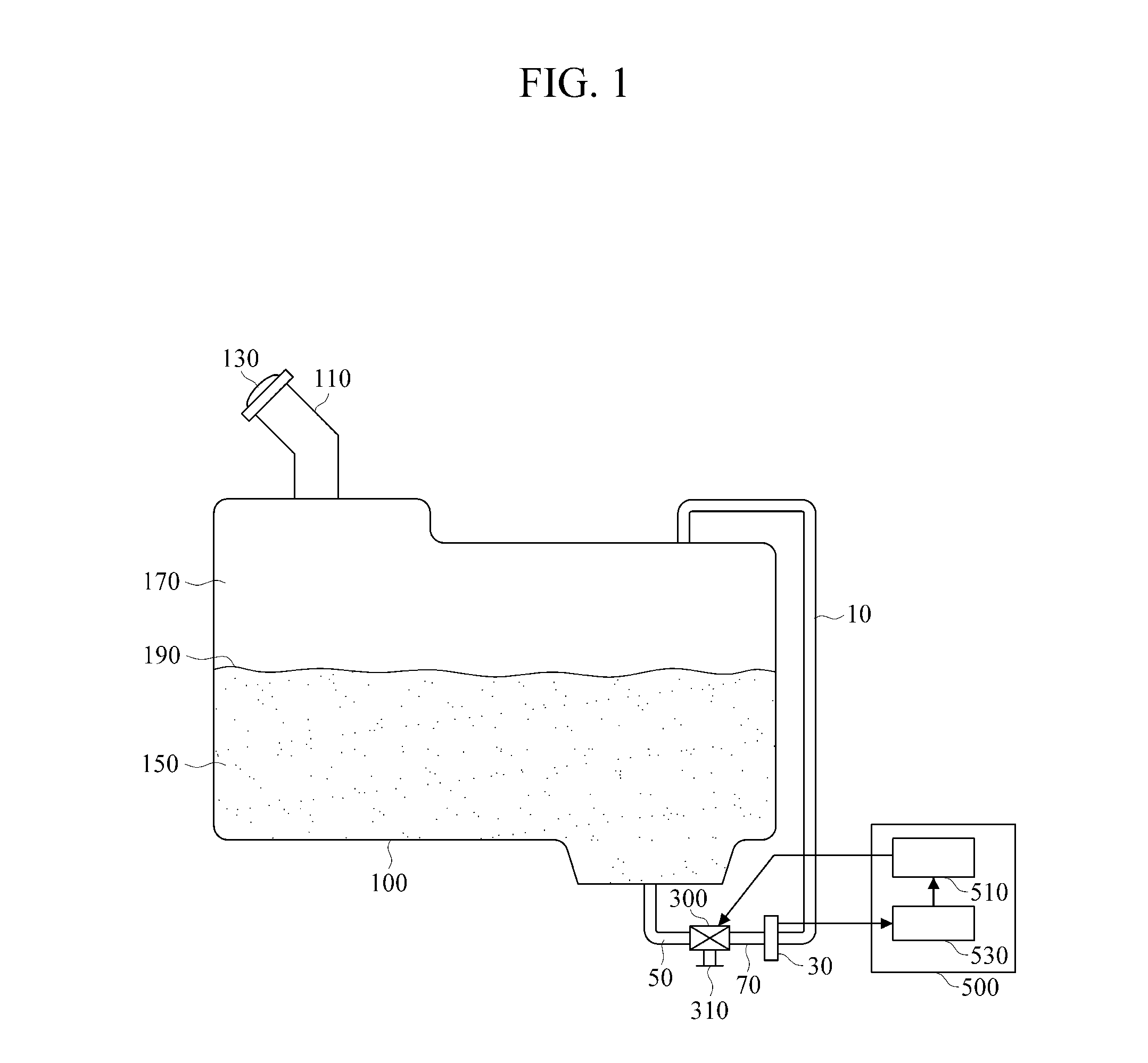
[0023]An integrated measuring apparatus may use a single pressure sensor to measure vaporized-gas pressure and differential pressure by means of a switching valve to switch between a path for measuring the vaporized-gas pressure and a path for measuring the differential pressure.

[0024]FIG. 1 is a block diagram illustrating an integrated measuring apparatus according to an exemplary embodiment of the present invention. Although FIG. 1 illustrates a fuel tank, the present invention may apply not only to the fuel tank but also to any...


PUM


Abstract

A technique for measuring vapor pressure and liquid level of a volatile liquid contained in a tank. An integrated measuring apparatus sequentially measures vapor pressure and differential pressure by use of a single pressure sensor and a switching valve which switches between paths for measurement of the vapor pressure and the differential pressure. In addition, the integrated measuring apparatus includes a pressure sensor configured to sequentially measure vapor pressure and total pressure or the combination of the vapor pressure and liquid pressure; and a switching valve configured to be connected to a vapor pressure tube and a liquid pressure tube and switch between connection paths with at least one input port of the pressure sensor, wherein the vapor pressure tube is connected to an upper part of the tank and the liquid pressure tube is connected to a lower part of the tank.

Description

BACKGROUND[0001]1. Field[0002]The following description relates to a measurement technique, and more particularly, to a technique for measuring vapor pressure and liquid level in a tank, such as an automobile fuel tank, which contains a volatile liquid.[0003]2. Description of the Related Art[0004]PCT Patent Publication No. 1990 / 008303 (published on Jul. 26, 1990) discloses a method for measuring the amount of liquid in a fuel tank by use of a differential pressure probe measuring a difference in pressure between an upper region and a lower region of the fuel tank. This method is advantageous in durability, as compared to a conventional floater-using measurement method, since it does not have an electrical contacting point. However the practical implementation of this method is not likely to be feasible because of the use of costly pressure sensor.[0005]There is a method for preventing a vaporized gas from flowing into the interior of a vehicle or out to the outside by measuring vapo...

Claims


Application Information

Patent Timeline
IPC IPC(8): G01F23/14
CPCG01F23/14G01F23/16G01F1/34G01L13/00G01D21/02
Inventor PARK, KYONG M.
Owner AUTO IND
Why Eureka
Try Eureka