
Drive for an Industrial Truck with Steering Support

a technology of steering support and industrial trucks, applied in vehicle components, control devices, transportation and packaging, etc., can solve the problems of high steering force, electric control of drive units, and requires a relatively complex design, and achieve simple construction design, simple and cost-effective design, and promote safe and intuitive control of industrial trucks.

Active Publication Date: 2014-07-17
ZF FRIEDRICHSHAFEN AG
View PDF13 Cites 6 Cited by
  • Summary
  • Abstract
  • Description
  • Claims
  • Application Information

AI Technical Summary

Benefits of technology

The invention is for industrial trucks that have a drive motor and a steering motor for moving the wheel. There is also a drawbar that controls both the direction and speed of movement. This allows for a simple and cost-effective drive for industrial trucks. The design also reduces maintenance costs and ensures safe and intuitive control of the truck. The motors used can be electric or hydraulic, and the use of hydraulic motors can lead to energy savings and longer run time for the truck.

Problems solved by technology

In the case of heavy industrial trucks, electrically controlled drive units are known for high loads and therefore high steering forces that arise on the drawbar.
For industrial trucks with electric steering support, the drive motor or traction drive motor, as the case may be, is connected in a torque-proof manner with the vehicle frame, which requires a relatively complex design for the mechanical connection of the drawbar with the transmission of the drive motor.
Such a complex control is intensive in terms of manufacturing costs, on the one hand, and maintenance, on the other hand, as, particularly in dirty environments of warehouses or the like, the moving parts of the shaft or the cardan shaft, as the case may be, must be lubricated on a regular basis.
At the same time, such complex mechanical redirections can degrade the usability of such an industrial truck if, for example, the steering axle around which a wheel of the drive of the industrial truck rotates upon a steering movement is offset to the axis of the point of application of the drawbar, as, at that point, a haptic feedback or a feedback of the steering movement, as the case may be, can no longer satisfactorily reflect the actual steering angle of the wheel under certain circumstances, which can lead to faulty operation.

Method used


Image

  • Drive for an Industrial Truck with Steering Support
  • Drive for an Industrial Truck with Steering Support
  • Drive for an Industrial Truck with Steering Support

Examples


Embodiment Construction

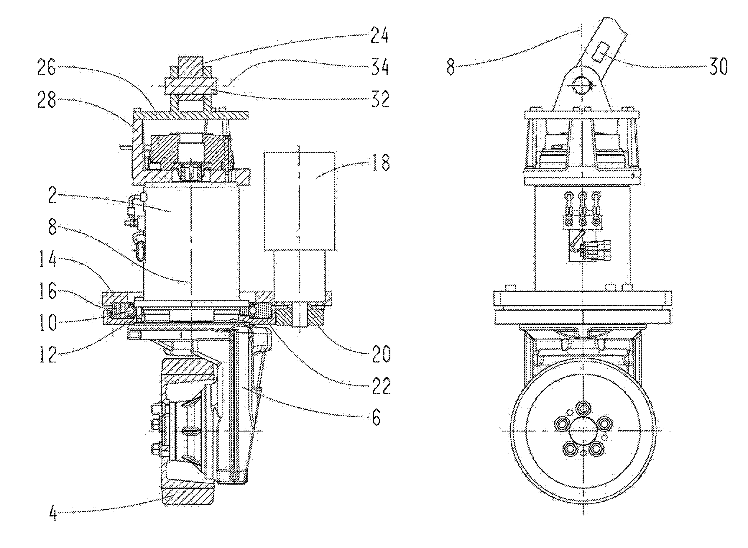
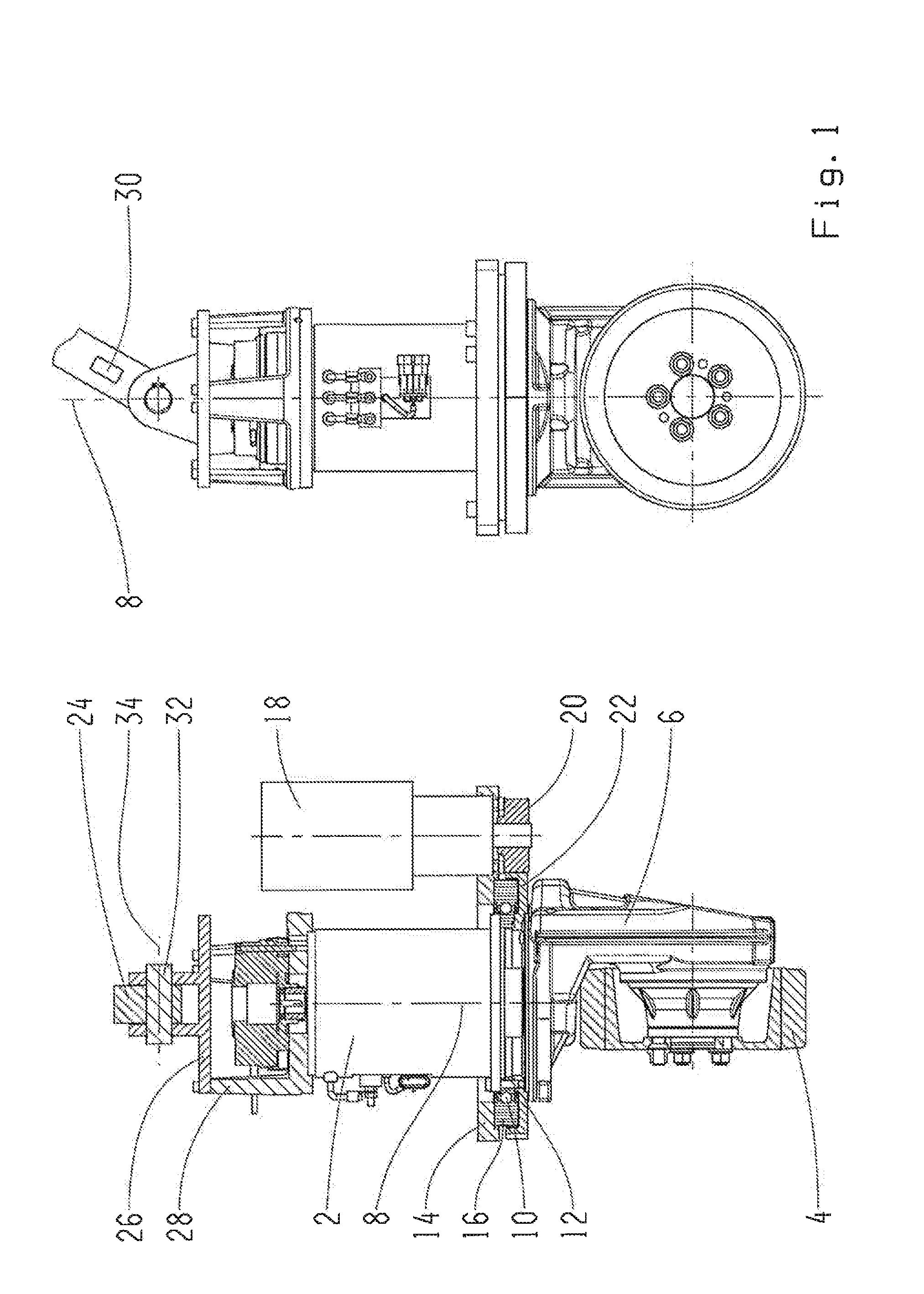
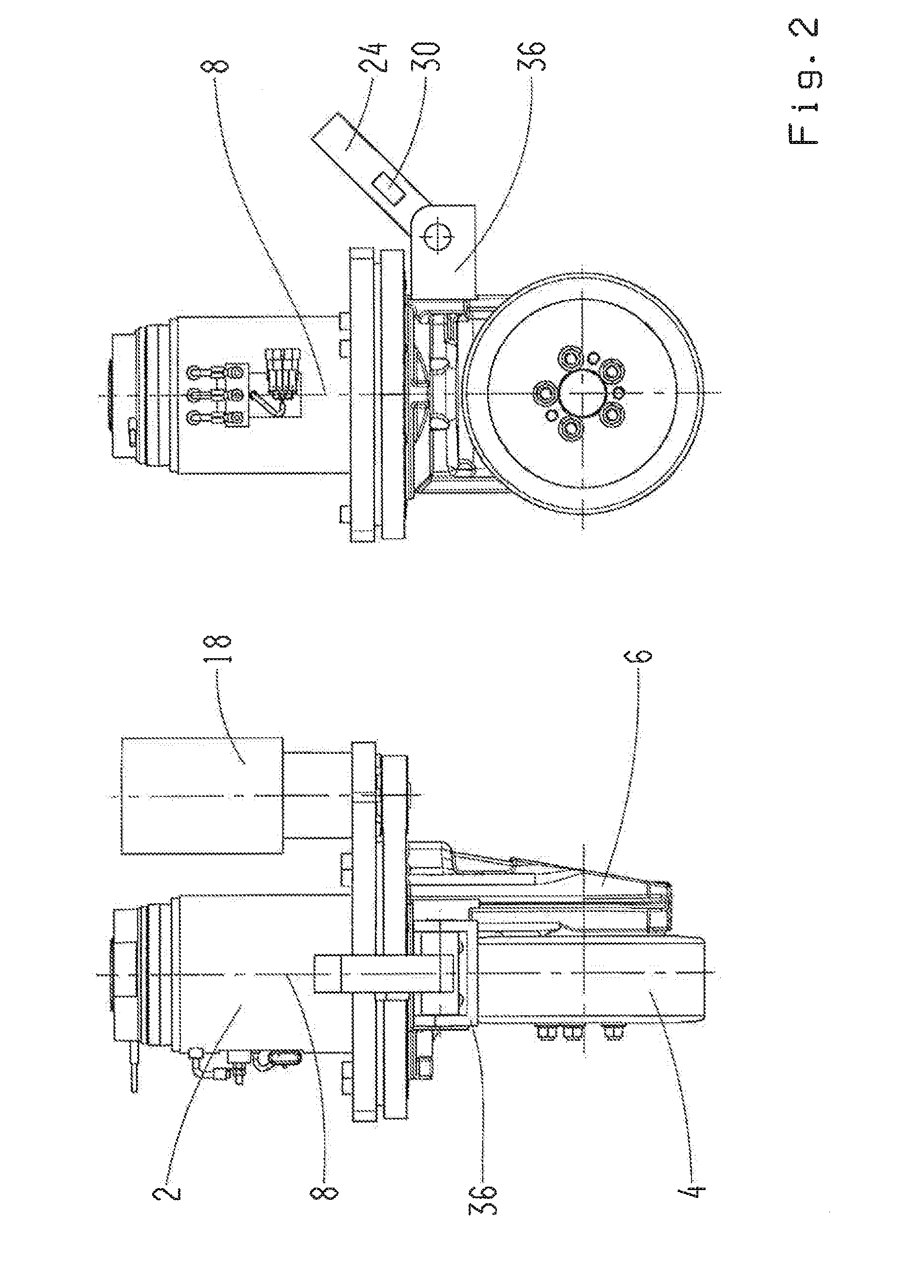
[0019]Reference will now be made to embodiments of the invention, one or more examples of which are shown in the drawings. Each embodiment is provided by way of explanation of the invention, and not as a limitation of the invention. For example features illustrated or described as part of one embodiment can be combined with another embodiment to yield still another embodiment. It is intended that the present invention include these and other modifications and variations to the embodiments described herein.

[0020]Exemplary embodiments are described with reference to the attached figures. It should be noted in advance that the figures are not necessarily drawn to scale and that, to emphasize certain features or properties, certain components may be artificially emphasized by using a different line thickness or hatching.

[0021]It is explicitly pointed out that additional embodiments are not to be restricted by the special implementations shown in the figures. In particular, the fact that...


PUM


Abstract

A drive for an industrial truck with at least one drive motor for driving a wheel of the industrial truck and at least one steering motor for supporting a steering movement of the wheel around a steering axle also features a drawbar for guiding the steering or driving movement by applying a load on the drawbar. The drive motor also rotates upon a steering movement of the wheel, whereas the drawbar is connected in a torque-proof manner, relative to the steering axle, with a component also rotating upon a steering movement of the wheel.

Description

FIELD OF THE INVENTION[0001]Embodiments of the present invention relate to a drive for an industrial truck, in particular a drive that provides steering support.[0002]BACKGROUND[0003]In warehousing and upon the transport of goods, hand-driven forklifts and industrial trucks, which are also known as lift trucks or pedestrian trucks, are used. In order to reduce the physical stress of an operator or a warehouse worker, such vehicles are often equipped with motors for driving support and / or steering support. Based on the preferred use in closed buildings and the emissions behavior, electric motors are frequently used both for the operation and for steering, for example as drive motors and steering motors for the support of steering movements.[0004]Traditional non-motorized supported industrial trucks usually feature a drawbar, which serves the purpose of specifying a steering direction or a driving direction by the operator.[0005]While, for systems purely driven by motors, the drawbar ...

Claims


Application Information

Patent Timeline
Patent Type & Authority Applications(United States)
IPC IPC(8): B60K17/30
CPCB60K17/30
Inventor STAMMBERGER, CHRISTIANBALD, DIRKHAMMER, MICHAEL
Owner ZF FRIEDRICHSHAFEN AG
Learn More