
System and Method for Removing Debris from a Downhole Wellbore

Inactive Publication Date: 2014-07-24
THRU TUBING SOLUTIONS
View PDF8 Cites 3 Cited by
  • Summary
  • Abstract
  • Description
  • Claims
  • Application Information

AI Technical Summary

Benefits of technology

The present invention is a system and method for removing debris from a downhole wellbore. The system includes a mandrel, a screen basket, and a nose member. The mandrel has a central passageway and is designed to be positioned at the upper end of a tubing string. The screen basket can be slidably disposed about the mandrel and is operable between an open position and a closed position. The screen basket can be sealed with the mandrel to create an annular space for retaining fines and debris. The nose member is located at the upper end of the mandrel and has one or more outlets for providing a stream of fluid. The system can be used to remove blockages of fines and debris from downhole wellbores and can be easily removed from the wellbore. The method involves introducing the system into the wellbore and circulating fluid through the system to disintegrate the blockage. The collected debris can then be removed from the wellbore.

Problems solved by technology

Recovering hydrocarbon gas from downhole environments can be problematic.
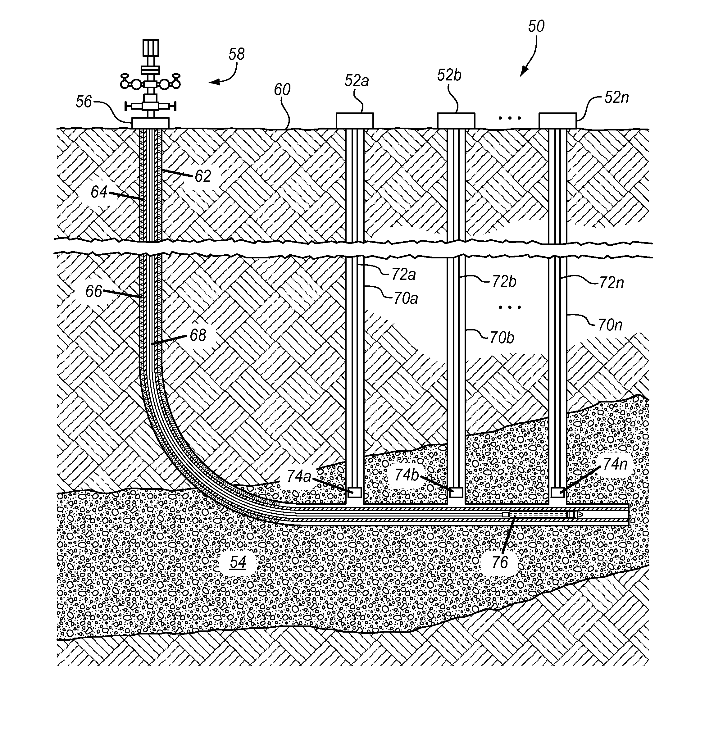
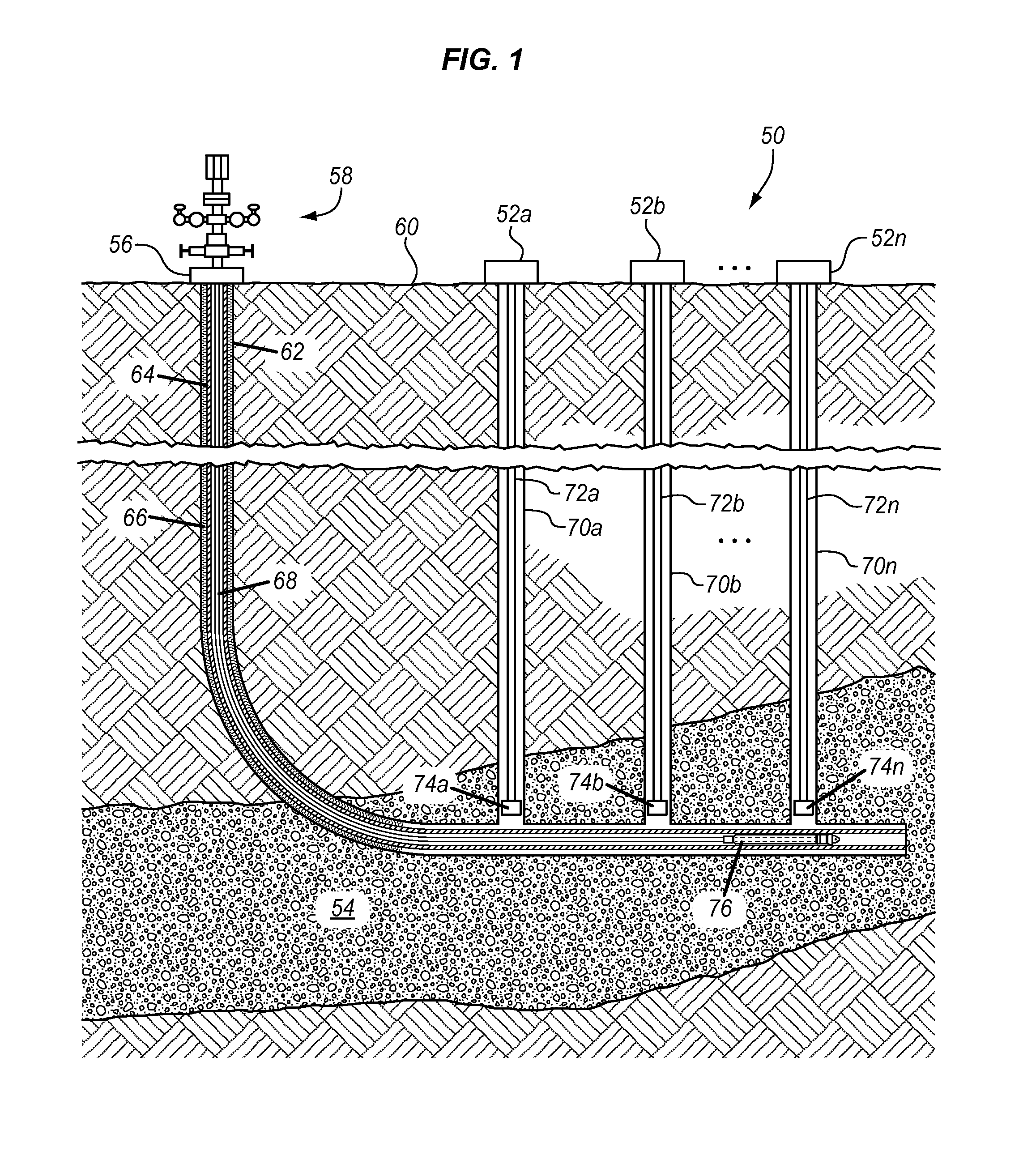
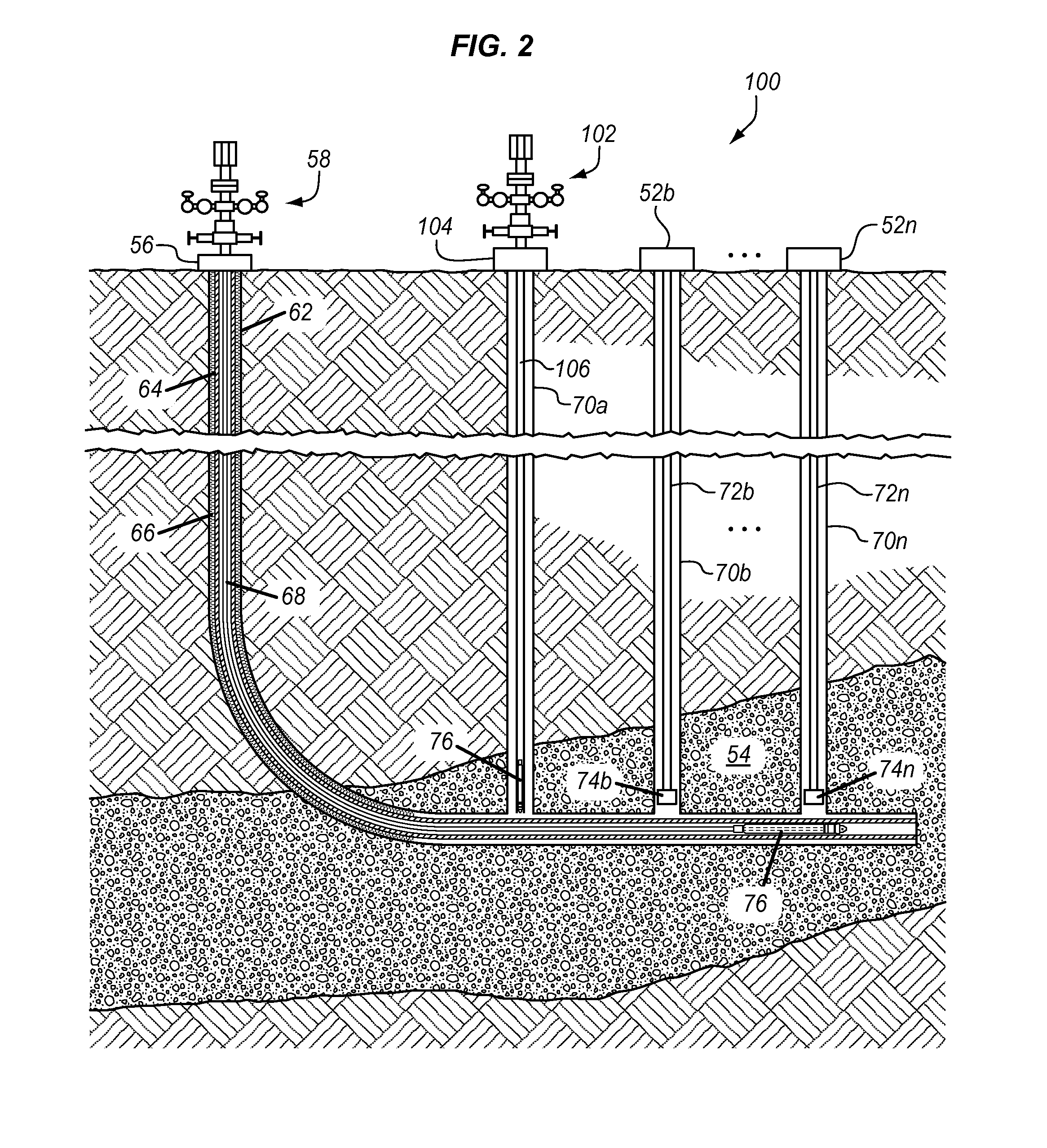
One problem associated with the de-watering process is that it creates a low bottom hole pressure in the downhole wellbore that causes fines and debris, drawn with the hydrocarbon gas, to accumulate in the horizontal wellbore.

Method used


Image

  • System and Method for Removing Debris from a Downhole Wellbore
  • System and Method for Removing Debris from a Downhole Wellbore
  • System and Method for Removing Debris from a Downhole Wellbore

Examples


Embodiment Construction

[0027]While the making and using of various embodiments of the present invention are discussed in detail below, it should be appreciated that the present invention provides many applicable inventive concepts which can be embodied in a wide variety of specific contexts. The specific embodiments discussed herein are merely illustrative of specific ways to make and use the invention, and do not limit the scope of the present invention.

[0028]In the following description of the representative embodiments of the invention, directional terms, such as “above,”“below,”“upper,”“lower,” etc., are used for convenience in referring to the accompanying drawings. In general, “above,”“upper,”“upward,” and similar terms refer to a direction toward the earth's surface along a wellbore, and “below,”“lower,”“downward,” and similar terms refer to a direction away from the earth's surface along the wellbore. Additionally, the term “proximal” refers to a linear, non-linear, or curvilinear distance or poin...


PUM


Abstract

A method for removing fines and debris from a downhole wellbore in a formation, including introducing a tubing string having a downhole debris removal tool disposed substantially near the lower end of the tubing string into the downhole wellbore; positioning the downhole debris removal tool substantially proximal to the fines and debris; circulating fluid through the downhole debris removal tool for disintegrating the fines and debris; and collecting the fines and debris in the downhole debris removal tool for removal out of the downhole wellbore.

Description

CROSS-REFERENCE TO RELATED APPLICATIONS[0001]This application claims the benefit of U.S. Provisional Application No. 60 / 804,789, filed 25 Mar. 2013. The entirety of this aforementioned application is incorporated herein by reference.TECHNICAL FIELD OF THE INVENTION[0002]This invention relates, in general, to a system and method for removing debris from a downhole wellbore.BACKGROUND OF THE INVENTION[0003]Without limiting the scope of the present invention, its background will be described in relation to a system and method for removing debris from a downhole wellbore, as an example.[0004]Recovering hydrocarbon gas from downhole environments can be problematic. For example, in coal seam gas recovery operations, water in the wellbores oftentimes impedes the gas recovery process in a particular hydrocarbon bearing formation. In some gas recovery or production processes, one or more horizontally drilled wellbores are intersected or connected with one or more vertical wellbores that cont...

Claims


Application Information

Patent Timeline
IPC IPC(8): E21B27/00
CPCE21B27/005E21B43/086E21B43/30
Inventor LOVING, STANLEY W.
Owner THRU TUBING SOLUTIONS
Learn More