Optical touch system, method of touch detection and computer program product

a technology of optical touch and touch detection, applied in the field of optical touch system and detection method, can solve the problems of increasing the size of the touch screen, the highest manufacturing cost of the capacitive touch screen among the different touch screens, and the limitation of the application of the capacitive touch screen

Active Publication Date: 2014-07-24
WISTRON CORP
View PDF2 Cites 1 Cited by
  • Summary
  • Abstract
  • Description
  • Claims
  • Application Information

AI Technical Summary

Benefits of technology

[0015]In an embodiment of the disclosure, the predetermined touch condition is that a signal intensity of the detecting signal is lower than a predetermined touch value, and the predetermined float condition is that a signal intensity of the detecting signal is higher than the predetermined touch value and lower than a predetermined float value.

Problems solved by technology

In the resistive, capacitive and rear projection touch screens that are conventionally used in the electronic products, the capacitive touch screen has the best touch-sensing performance, however, the manufacturing cost of the capacitive touch screen is the highest among the different touch screens.
Furthermore, the applications for the capacitive touch screen are limited with the increase of the size of the touch screen.
Moreover, along with the number of functions increasing in the electronic products, the touch operating method is no longer satisfying the demands from users on operating.
However, when the object is slightly distant from the sensing device, the capacitive floating touch sensing device is prone to determine as no object due to the rapid declined in capacitance, and thus an error in detection or insensitivity is prone to occur during an operation.

Method used


Image

  • Optical touch system, method of touch detection and computer program product
  • Optical touch system, method of touch detection and computer program product
  • Optical touch system, method of touch detection and computer program product

Examples


Embodiment Construction

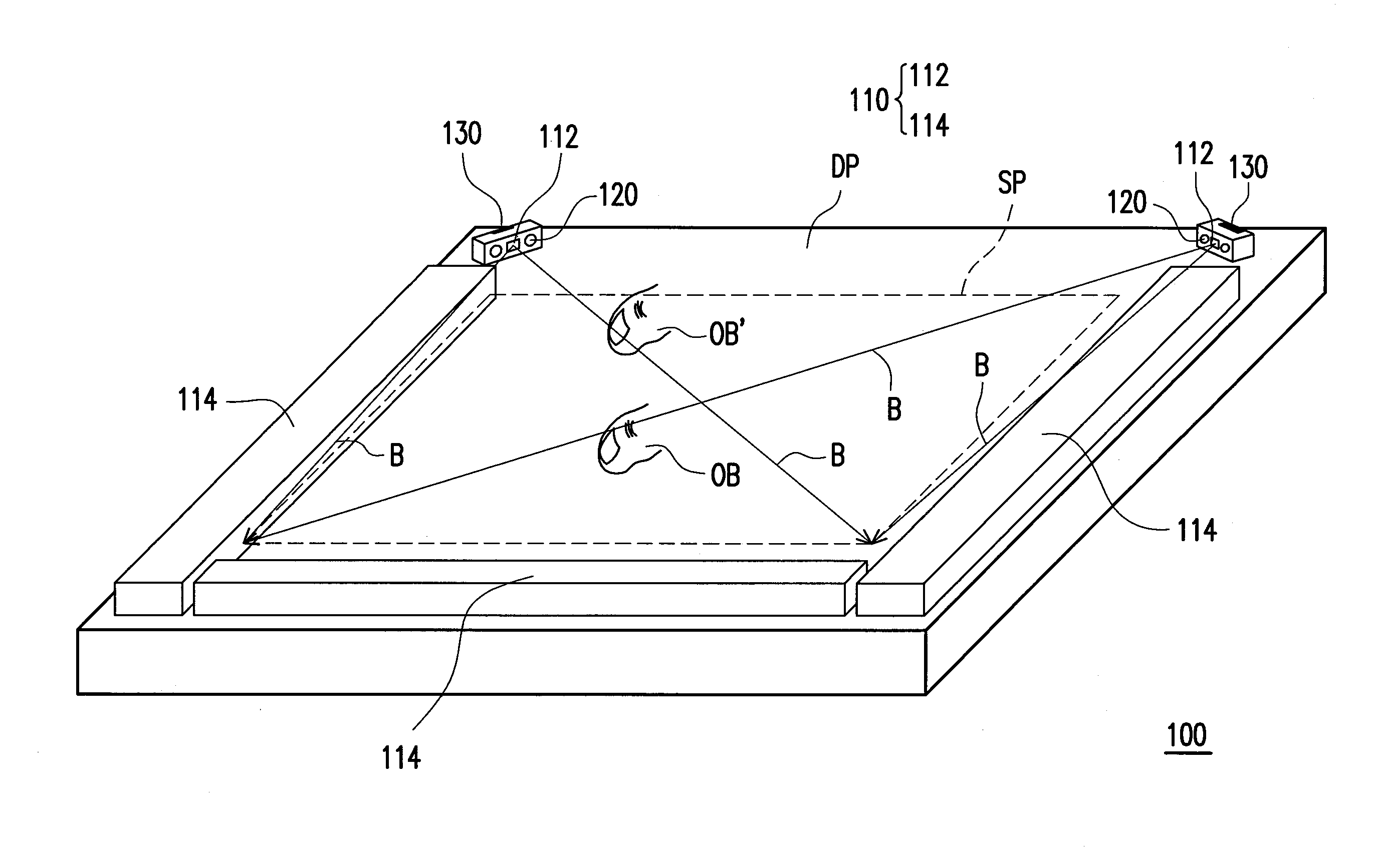
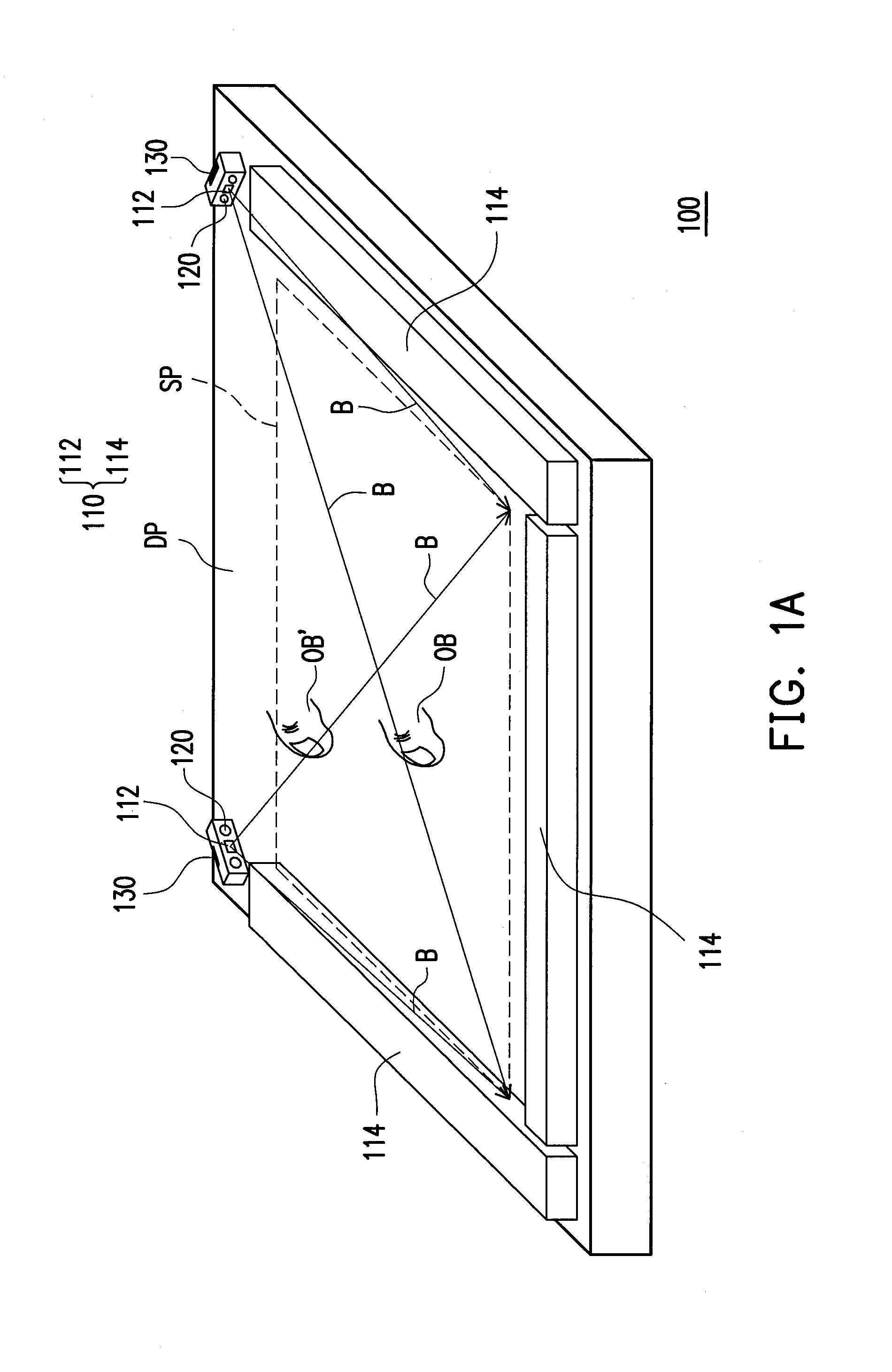
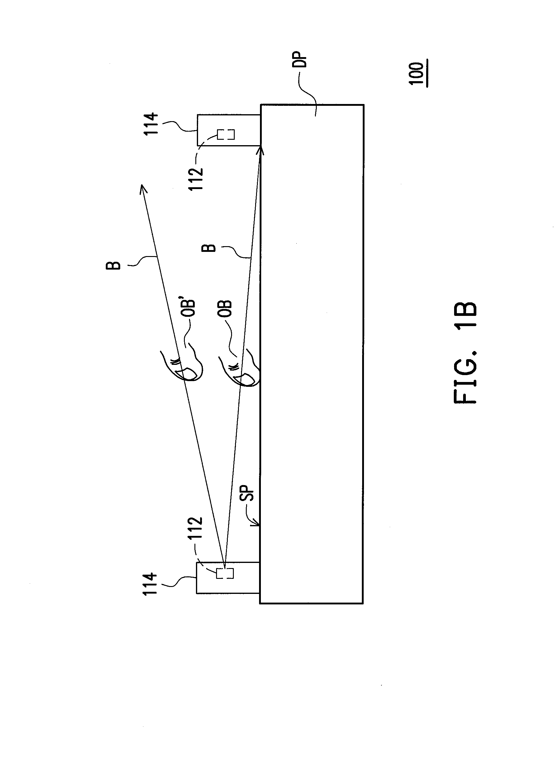
[0044]FIG. 1A is a schematic diagram showing an optical touch system according to an embodiment of the disclosure, and FIG. 1B is a side-view schematic diagram showing an optical touch system according to the embodiment shown in FIG. 1A. Referring to FIG. 1A and FIG. 1B together, in the embodiment, the optical touch system 100 can be configured to determine an action of an object OB (such as the finger depicted in FIG. 1A and FIG. 1B, alternatively, can also be other objects capable of obstructing lights) approaching or touching a base plane SP, in which the base plane SP can be a display surface of a display apparatus depicted in FIG. 1A, although the disclosure is not limited thereto. The optical touch system 100 includes a light source module 110, at least one image detecting module 120 and a processing unit 130. The light source module 110 is disposed beside the base plane SP, and provides a detecting light B. The detecting light B is transmitted in front of the base plane SP. T...


PUM


Abstract

An optical touch system includes a light source module, at least one image detecting module and a processing unit. The light source module provides a detecting light. The detecting light is transmitted in front of the base plane. The image detecting module detects an intensity variation of the detecting light. The image detecting module generates a detecting signal corresponding to the detecting light. When an object approaches or touches the base plane, at least a portion of the detecting light is obstructed by the object. The processing unit determines a position of the object with respect to the base plane according to the detecting signal, and determines that the object approaches or touches the base plane according to an intensity of a portion of the detecting signal corresponding to an obstruction position of the object. A method of touch detection and a computer program product are also provided.

Description

CROSS-REFERENCE TO RELATED APPLICATION[0001]This application claims the priority benefit of Taiwan application serial no. 102102067, filed on Jan. 18, 2013. The entirety of the above-mentioned patent application is hereby incorporated by reference herein and made a part of this specification.BACKGROUND OF THE DISCLOSURE[0002]1. Field of the Disclosure[0003]The disclosure relates to a touch system, and more particularly, to an optical touch system.[0004]The disclosure relates to a method of detection, and more particularly, to a method of touch detection.[0005]The disclosure relates to a computer program product, and more particularly, to a computer program product for determining an action of an object approaching or touching a base plane.[0006]2. Description of Related Art[0007]In recent years, touch electronic products are favored by consumers due to convenience operation and high intuitiveness, and have gradually become the mainstream in the market. In the resistive, capacitive a...

Claims


Application Information

Patent Timeline
Patent Type & Authority Applications(United States)
IPC IPC(8): G06F3/042
CPCG06F3/0421G06F3/0428
Inventor CHEN, YU-YEN
Owner WISTRON CORP
Why Eureka
Try Eureka