Stepped-decay video morphing for liquid crystal displays

a liquid crystal display and video morphing technology, applied in the field of displays, can solve the problems of affecting the display effect or data, affecting the display effect, and affecting the display effect, and achieve the effect of decreasing the signal intensity

Inactive Publication Date: 2005-06-21
BAE SYST INFORMATION & ELECTRONICS SYST INTERGRATION INC
View PDF8 Cites 9 Cited by
  • Summary
  • Abstract
  • Description
  • Claims
  • Application Information

AI Technical Summary

Benefits of technology

[0017](d) decreasing the signal intensity for the first pixel position from an intermediate intensity to the NEW pixel intensity.

Problems solved by technology

However, that is typically not true for an LCD.
This anomaly, which can both distract the viewer and make observation of displayed effects or data more difficult, may also be referred to as a blink anomaly.
As such, this prior approach is seen as inadequate to be fully responsive to anomalies actually experienced by a particular viewer under varying operating conditions, as well as to visual response and actual perception of a viewer.

Method used


Image

  • Stepped-decay video morphing for liquid crystal displays
  • Stepped-decay video morphing for liquid crystal displays
  • Stepped-decay video morphing for liquid crystal displays

Examples


Embodiment Construction

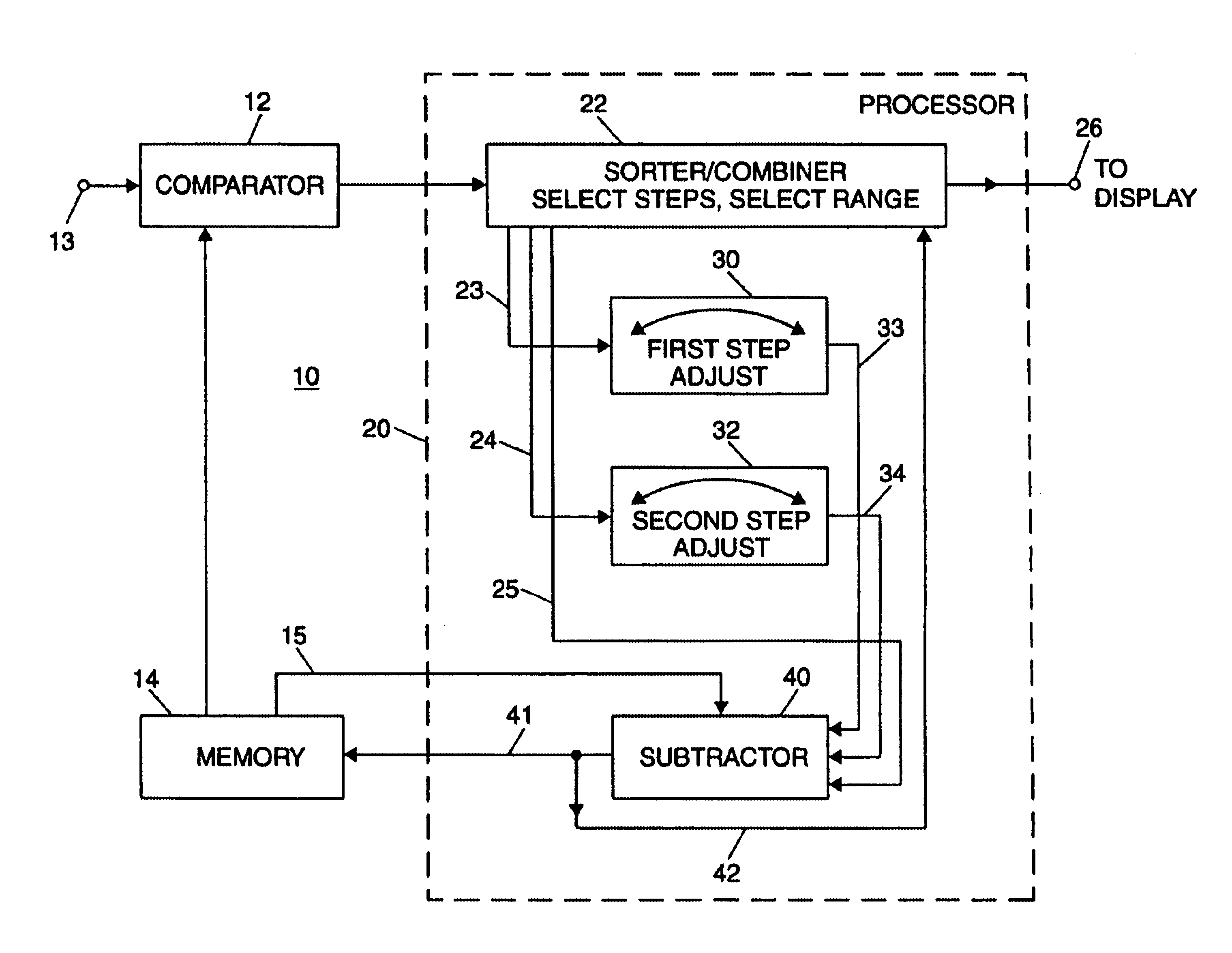
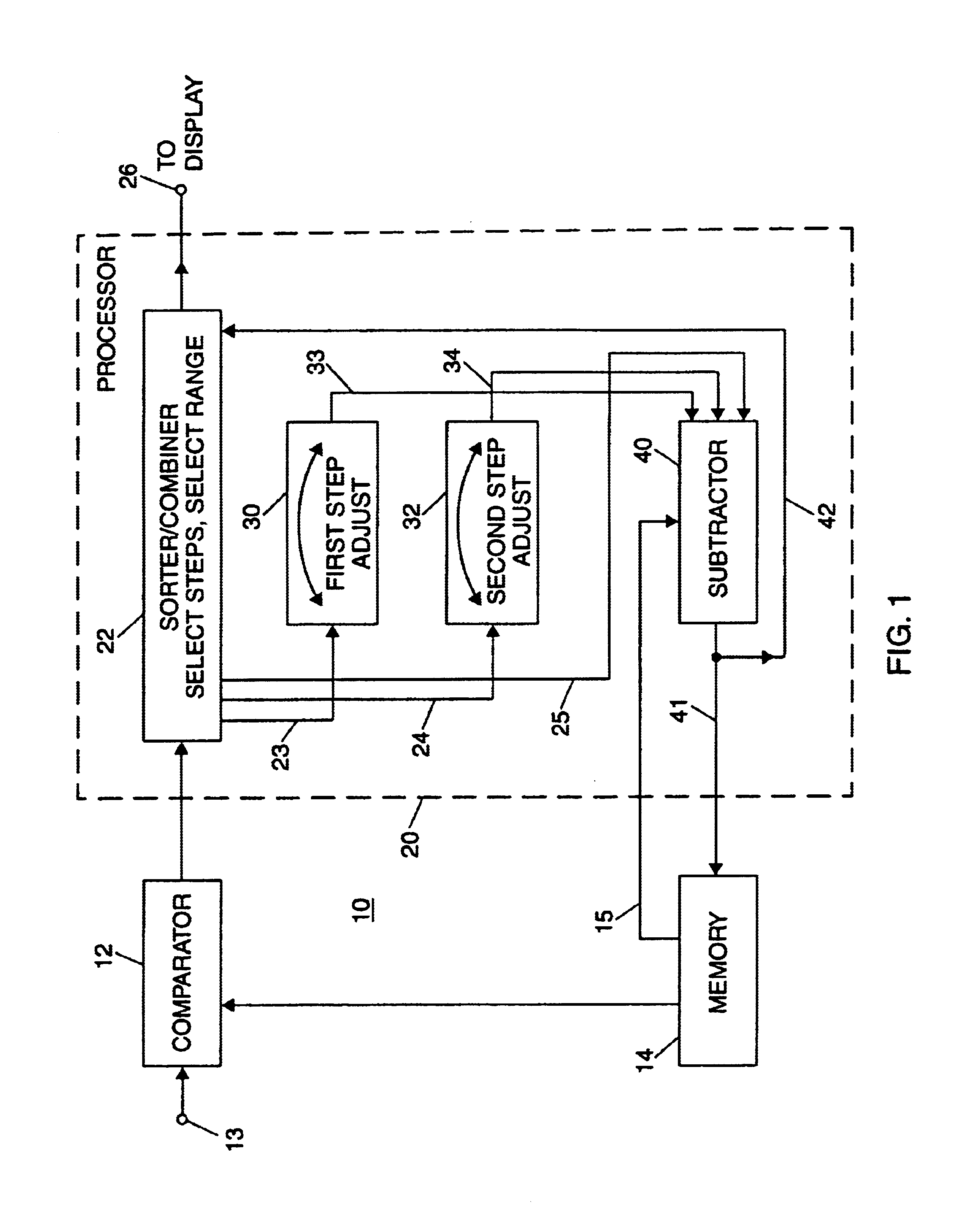
[0029]FIG. 1 illustrates an embodiment of a stepped-decay video morphing system 10, to modify video signals for use with a display (such as an LCD display) having disparate turn-on / turn-off characteristics. These characteristics may be represented by a faster turn-off time for a particular pixel position to transition from high intensity light output to low intensity light output, relative to a slower turn-on time to transition from low intensity to high intensity, for example. As shown, system 10 includes a comparator 12 to compare, on a pixel-by-pixel basis, signal intensity for a new image to signal intensity for a prior image. This is typically carried out on a frame-by-frame basis, even though image content may change less rapidly (e.g., a new image every four frames). More particularly, comparator 12 is arranged to compare, for a first pixel position, the signal intensity for a new image (termed “NEW” pixel intensity) to the signal intensity for a prior image (termed “OLD” pix...


PUM


Abstract

An LCD display has disparate turn-on/turn-off characteristics whereby a rapid decrease in signal intensity at pixel positions can cause a flash effect. Such effect is avoided or reduced for a video signal including a large intensity decrease between successive images. By incrementally decreasing the signal intensity over three frames, rather than from one frame to the next, intermediate intensity steps reduce the frame-to-frame magnitude of intensity decrease. A key feature is selection of the size of the intermediate intensity step changes on a closed loop basis, by an operator viewing the image effects resulting from the operator's adjustments. Flash effects in particular applications may be affected by image content, incident light and other local conditions as well as by subjective viewer characteristics and preferences. By operator adjustment, while viewing the resulting display, the best presentation can be provided. The operator can also select the number of steps over which an intensity decrease is incrementally introduced.

Description

RELATED INVENTIONS[0001](Not Applicable)FEDERALLY SPONSORED RESEARCH[0002](Not Applicable)BACKGROUND OF THE INVENTION[0003]This invention relates to displays subject to visual anomalies resulting from differences in the time required to increase and decrease light output for individual pixel positions and, more particularly, to compensation for such anomalies in operation of liquid crystal and other displays.[0004]A liquid crystal display (LCD) in a flat display format capable of displaying monochromatic, partial color, or full color images can be utilized in a variety of applications. Cathode ray tube (CRT) type displays provide images with pixel luminance responses capable of tracking rapid frame-to-frame changes in signal intensity of a video signal. However, that is typically not true for an LCD. Depending on the specifics of particular LCD constructions, configurations and excitation conditions, the luminance response of an LCD may be characterized by a disparity between lumina...

Claims


Application Information

Patent Timeline
Patent Type & Authority Patents(United States)
IPC IPC(8): G09G5/10G09G3/20G09G3/36
CPCG09G3/3611G09G3/2007G09G2340/16G09G2320/0247
Inventor LIBRANDI, RICHARD N.BROFKA, RICHARD F.ANDERSON, GUSTAV A.HEINICKE, ERIC O.ZELO, JOSEPH L.
Owner BAE SYST INFORMATION & ELECTRONICS SYST INTERGRATION INC
Why Eureka
Try Eureka