Magnetic resonance imaging apparatus

a magnetic resonance imaging and apparatus technology, applied in the field of magnetic resonance imaging apparatus, can solve the problems of difficult visualization of turbulent parts, inconvenient use, and difficulty in visualizing peripheral blood vessels such as perforating branches, and achieve the effects of reducing signal intensity, high signal intensity, and low signal intensity

Active Publication Date: 2008-05-22
TOSHIBA MEDICAL SYST CORP
View PDF9 Cites 35 Cited by
  • Summary
  • Abstract
  • Description
  • Claims
  • Application Information

AI Technical Summary

Benefits of technology

[0015]On the other hand, there has been a desire to obtain useful information which has not been obtained from magnetic resonance signals independently collected by dephase or rephase.
[0016]According to a first aspect of the present invention, there is provided a magnetic resonance imaging apparatus comprising: an acquisition unit which acquires first data in which a tissue of interest has higher signal intensity than a background and second data in which the tissue of interest has lower signal intensity than the background, with regard to images of the same region of the same subject; and a generation unit which generates, on the basis of the first data and the second data, third data in which the contrast of the tissue of interest to the background is higher than those in the first and second data.
[0017]According to a second aspect of the present invention, there is provided a magnetic resonance imaging apparatus comprising: an acquisition unit which acquires first data in which a tissue of interest has a higher signal intensity than a background and second data in which the tissue of interest has a lower signal intensity than the background, with regard to images of the same region of the same subject; and a generation unit which generates third data indicating an image, the image being a composition of an image indicated by the first data and an image indicated by the second data to which different colors are allocated.
[0018]According to a third aspect of the present invention, there is provided a magnetic resonance imaging apparatus comprising: a scan unit which executes, with regard to a region of interest of a subject, a first scan for data collection by a pulse sequence to obtain first image data in which blood vessel has a higher signal intensity than a background, and a second scan for collection by a pulse sequence different from that of the first scan to obtain second image data in which the blood vessel has a higher signal intensity than the background; and a generation unit which generates, on the basis of the first image data and the second image data, third image data in which the contrast of the blood vessel to the background is higher than those in the first and second image data.
[0019]According to a fourth aspect of the present invention, there is provided a magnetic resonance imaging apparatus comprising: a scan unit which executes, with regard to a region of interest of a subject, a first scan for data collection by a pulse sequence to obtain first image data in which blood vessel has a lower signal intensity than a background, and a second scan for collection by a pulse sequence different from that of the first scan to obtain second image data in which the blood vessel has a lower signal intensity than the background; and a generation unit which generates, on the basis of the first image data and the second image data, third image data in which the contrast of the blood vessel to the background is higher than those in the first and second image data.

Problems solved by technology

In this non-contrast TOF method, it is difficult to visualize turbulent parts, and peripheral blood vessels such as perforating branches are not easily visualized.
The FSE method was initially used in a sequence of the BB method, but is not used very widely due to the problem of image processing, or other problems.
In the BE method, peripheral tissues also show low signal intensity, and it is therefore difficult to separately visualize the blood vessels alone.
For example, it is difficult to exclude air by minimum intensity projection (mimIP) in the BB method.
However, it has been difficult in both the WB method and the BB method to clearly visualize various structures of blood vessels.
However, there is a limit to information that can be obtained from the magnetic resonance signals collected by dephase or rephase, therefore it has been impossible to obtain information necessary to satisfactorily visualize, for example, blood vessels.

Method used


Image

  • Magnetic resonance imaging apparatus
  • Magnetic resonance imaging apparatus
  • Magnetic resonance imaging apparatus

Examples


first embodiment

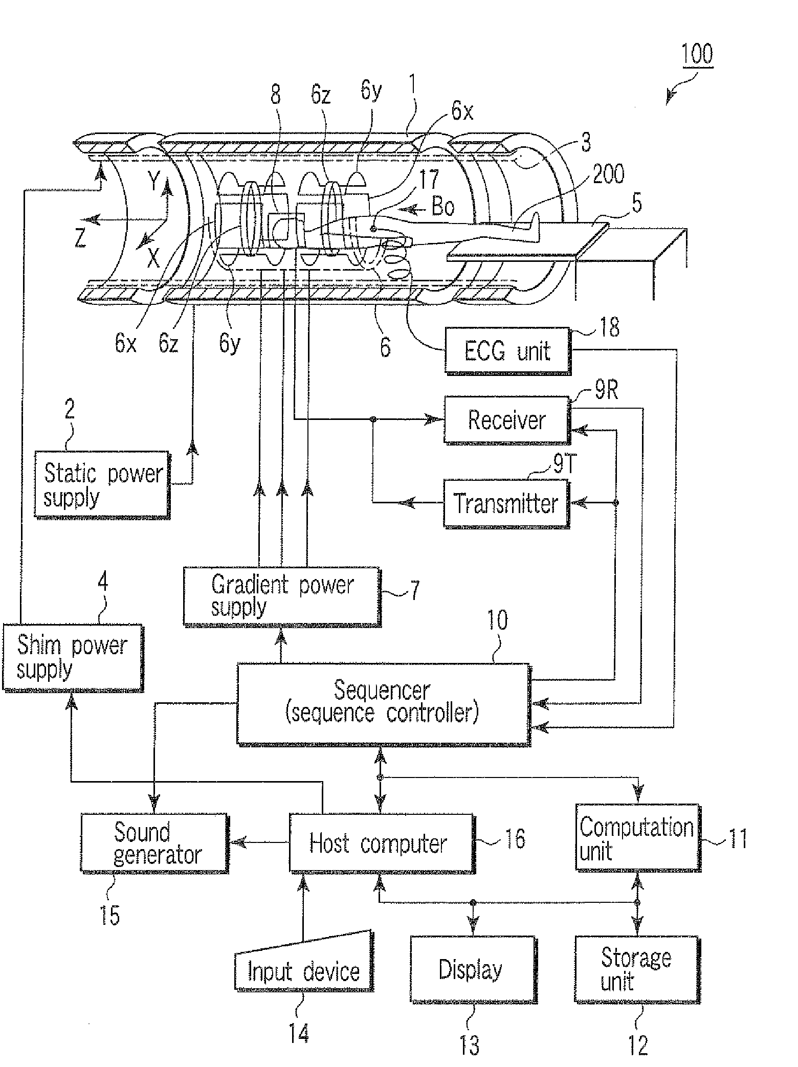
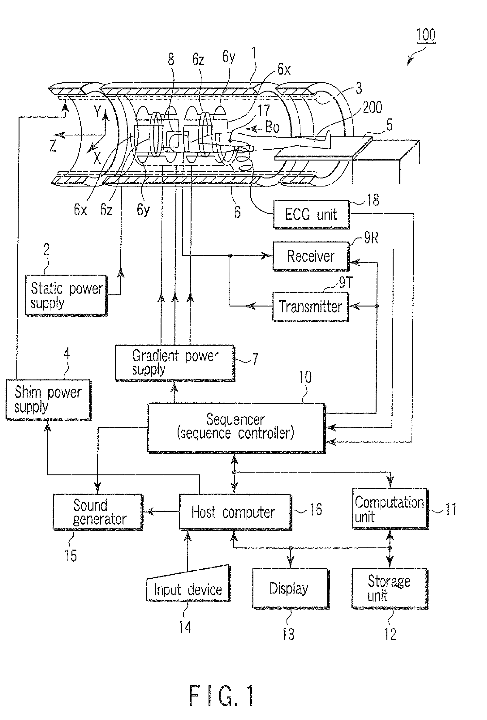
[0065]The operation of the MRI apparatus 100 configured as described above in a first embodiment will next be described. It is to be noted that the MRI apparatus 100 can perform various kinds of imaging achieved by existing MRI apparatuses, which is, however, not described. Here, an operation in the case of obtaining hybrid MRA is explained.

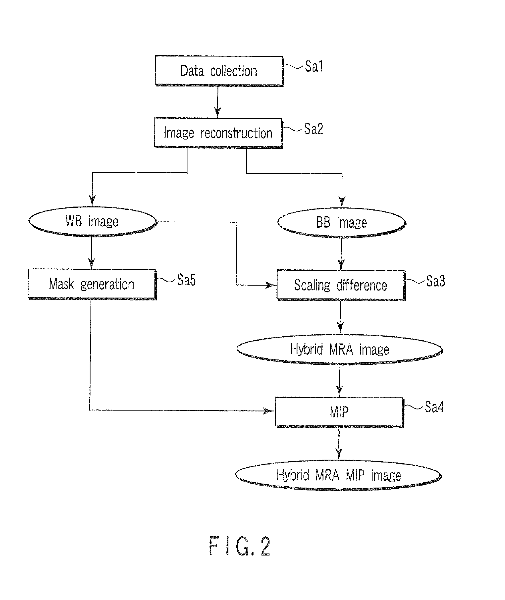
[0066]FIG. 2 is a flowchart showing a procedure for operating the MRI apparatus 100 when the hybrid MRA is obtained.

[0067]In step Sa1, the sequencer 10 controls the gradient power supply 7, the transmitter 9T and the receiver 9R to collect data in both a WB method and a BB method. The data collection in the WB method and the data collection in the BB method may be carried out in separate sequences, but a multi-echo method is used here to carry out the data collection in both the NB method and the BB method in a series of sequences. The data collection is carried out for each of a plurality of slices in a slab set as an imaging region.

[0068]It is ...

second embodiment

[0125]The operation of the MRI apparatus 100 in a second embodiment will next be described.

[0126](A) Theoretical Preparation

[0127]As a theoretical preparation before the description of the specific operation, there are defined an MR signal model of a voxel with uneven magnetic susceptibility and with a flow, and rephase / dephase signal models.

[0128](A-1) MR Signal Model of Voxel with Uneven Magnetic Susceptibility and with Flow

[0129]First, parameters regarding the MR signal model of a voxel with uneven magnetic susceptibility and with a flow are defined as follows:

[0130]M0: Proton density

[0131]AT1: T1 dependent attenuation

AT1=1−exp(−TR / T1)

[0132]AT2: T2 dependent attenuation

AT2=exp(−TE / T2)

[0133]AD: Diffusion dependent attenuation

AD=exp(−bD)

[0134]Asus: Susceptibility dependent attenuation

Asusexp[−TE(γΔB0σ)]*

[0135]Φsus: Susceptibility dependent phase

 sus=−TE(γΔB0m)

[0136]However, in the case of Lorenzian model

[0137]T2*: Relaxation time including T2 and a component generated by a suscepti...


PUM


Abstract

A magnetic resonance imaging apparatus includes an acquisition unit which acquires first data in which a tissue of interest has higher signal intensity than a background and second data in which the tissue of interest has lower signal intensity than the background, with regard to images of the same region of the same subject, and a generation unit which generates, on the basis of the first data and the second data, third data in which the contrast of the tissue of interest to the background is higher than those in the first and second data.

Description

CROSS-REFERENCE TO RELATED APPLICATIONS[0001]This application is based upon and claims the benefit of priority from prior Japanese Patent Applications No. 2006-315823, filed Nov. 22, 2006; and No. 2007-119883, filed Apr. 27, 2007, the entire contents of both of which are incorporated herein by reference.BACKGROUND OF THE INVENTION[0002]1. Field of the Invention[0003]The present invention relates to a magnetic resonance imaging apparatus which obtains information for medical diagnoses on the basis of a magnetic resonance signal emitted from a subject.[0004]2. Description of the Related Art[0005]MR angiography (MRA) is a magnetic resonance imaging method intended for arteries and veins. MRA includes a time of flight (TOF) method using a gradient echo (GRE) method, and a black-blood (BB) method using a fast spin echo (FSE) method for visualizing a blood vessel at low signal intensity. Recently, a susceptibility-weighted imaging (SWI) method which applies the susceptibility effect of ve...

Claims


Application Information

Patent Timeline
Patent Type & Authority Applications(United States)
IPC IPC(8): A61B5/05
CPCA61B5/055A61B5/417A61B5/489G01R33/50G01R33/5635G01R33/5607G01R33/5608G01R33/5616G01R33/56308G01R33/5601G01R33/56536
Inventor KIMURA, TOKUNORIIKEDO, MASATO
Owner TOSHIBA MEDICAL SYST CORP
Why Eureka
Try Eureka