Bonding station for two different bonding processes
a technology of tubular packaging and bonding station, which is applied in the direction of sausage casing manufacturing, mechanical working/deformation, paper/cardboard wound articles, etc., can solve the problem that the machine takes less work space in the production line, and achieve the effect of facilitating the removal of adhesive residuals from the bonding tool
- Summary
- Abstract
- Description
- Claims
- Application Information
AI Technical Summary
Benefits of technology
Problems solved by technology
Method used
Image
Examples
second embodiment
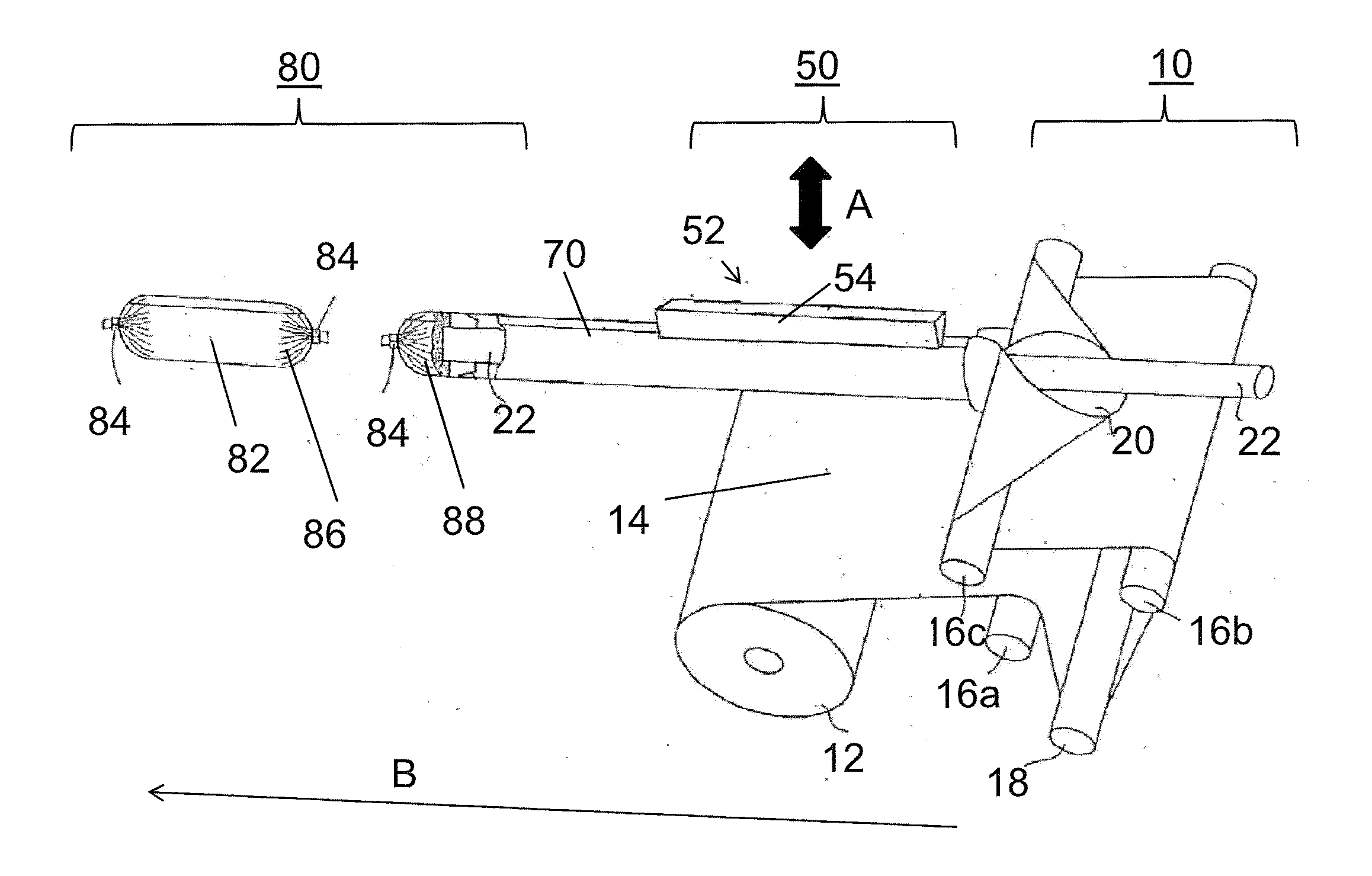
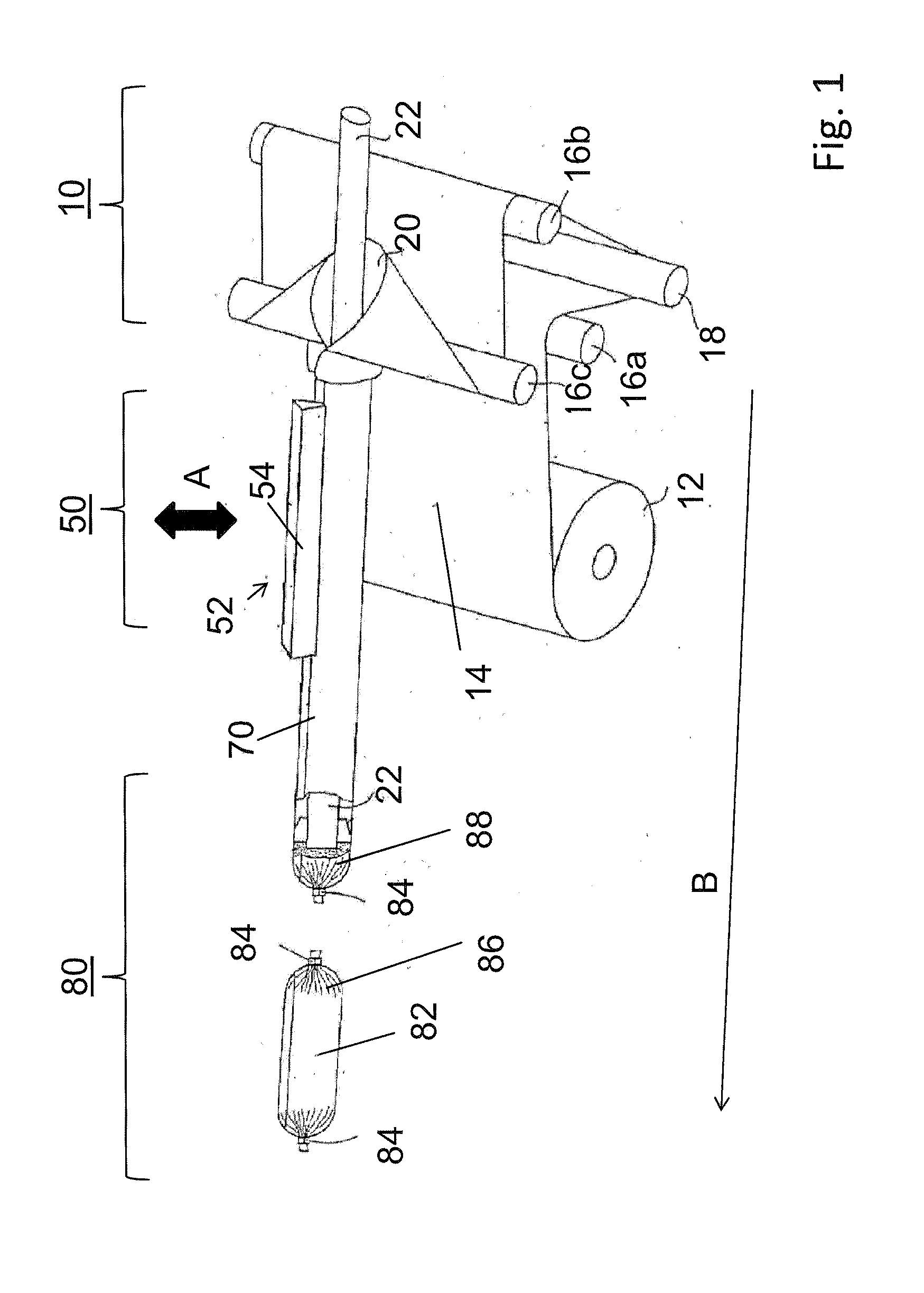
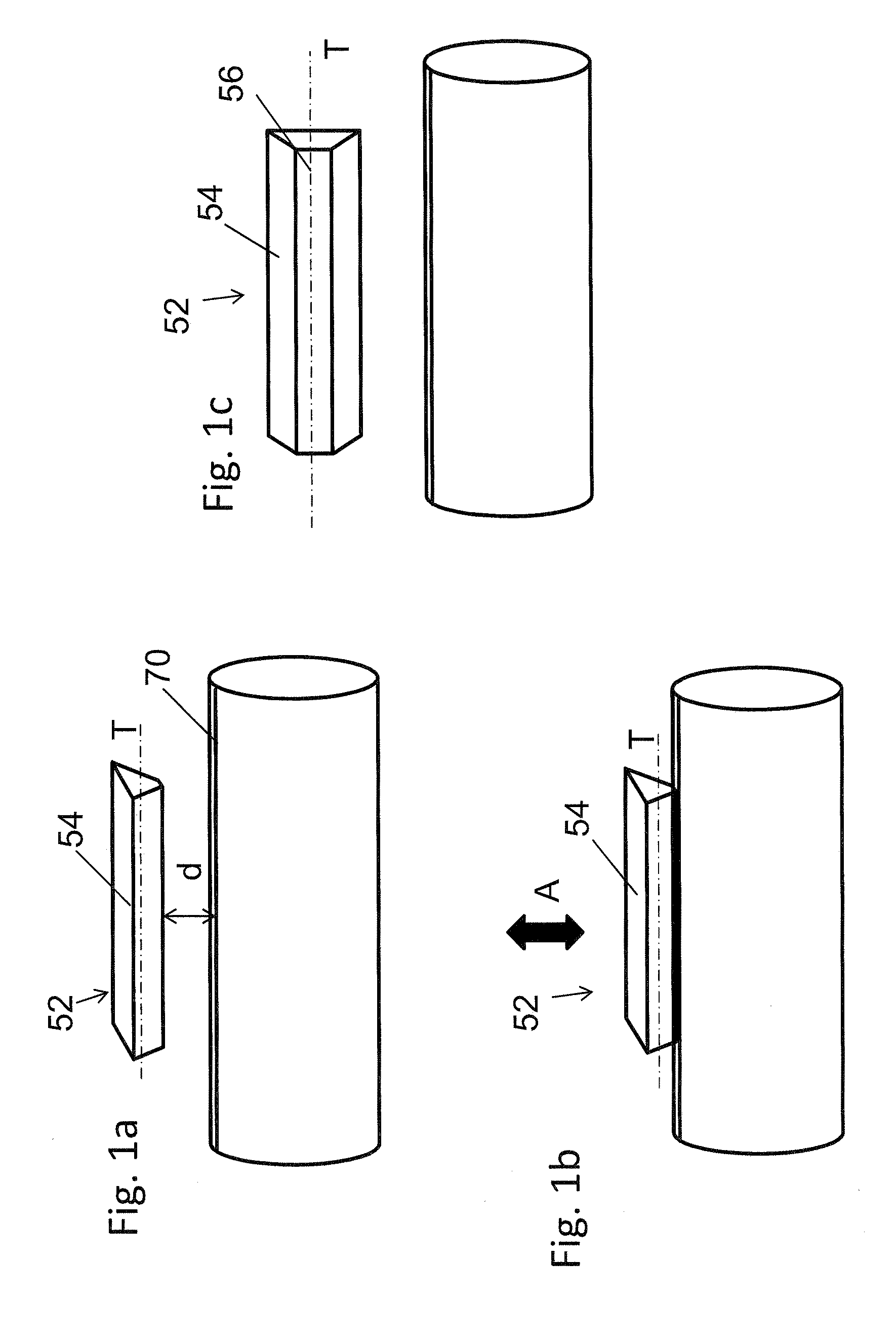
[0081]In case, the bonding process shall be changed from bonding by heat sealing to adhesive bonding, this can be performed as already explained together with FIG. 1. Bonding tool 152 of FIG. 2 is moved in direction A normal to feeding direction B towards the edge areas of tubular packaging casing 70 to be bonded. This movement as well as the temperature of bonding tool 152 and the pressure exerted by bonding tool 152 onto film web 14 to be bonded is controlled by the device for controlling, as already explained for FIG. 1 above. The temperature of bonding tool 152 is controlled, because it is possible to use hot as well as cold curing adhesives for bonding the edge areas.
[0082]In case, the bonding process shall be changed from bonding by adhesive bonding with bonding tool 152 being in the second working position to bonding by heat sealing bonding with bonding tool 152 being in the first working position, some steps need to be performed. These steps correspond to the steps already e...
third embodiment
[0084]FIG. 3 shows the present invention. FIG. 3a, shows a side view of FIG. 3. A bonding tool 252 comprises a rolling element in form of a heating / pressurizing roller 254, that may be heated up onto a temperature when being in the first working position for performing the heat sealing bonding. In its second working position, bonding tool 252, in particular heating / pressurizing roller 254, may be pressed against an object against which heating / pressurizing roller 254 can roll of. At least one guide lever 256, in particular two guide levers 256, is / are adapted to hold heating / pressurizing roller 254 by means of a roller shaft 258. Roller shaft 258 represents the axis of rotation of heating / pressurizing roller 254, and enables a rolling movement of heating / pressurizing roller 254 independent from rotationally rigid guide levers 256. Bonding tool 252 can be moved at least along direction A being substantially normal to feeding direction B by means of the actuator moving bonding tools 5...
fourth embodiment
[0087]In the present invention as shown in FIG. 4, a bonding tool 352 provides at least two rolling elements. As can be seen in FIG. 4, four heating / pressurizing rollers 354 are part of bonding tool 352. FIG. 4a shows a side view of FIG. 4. At least one guide lever 356 is provided for heating / pressurizing rollers 354, each. Guide rollers 356 are bound together by a guide bar 358 having longitudinal axis T being parallel to feeding direction B. Guide bar 358 is pivotably moveable around a pivoting axis P being transverse to longitudinal axis T of bonding tool 352 by a pivoting actuator (not shown). Bonding tool 352 is moveable along direction A substantially normal to feeding direction B by means of the actuator as already explained with FIGS. 1 to 3. In general, the change of working positions from the first to the second working position and vice versa follows the proceedings as already introduced with FIGS. 1 to 3, too. Additionally, the pivoting movement of bonding tool 352 aroun...
PUM
| Property | Measurement | Unit |
|---|---|---|
| rotational angle | aaaaa | aaaaa |
| areas | aaaaa | aaaaa |
| pressure | aaaaa | aaaaa |
Abstract
Description
Claims
Application Information
 - R&D
- Intellectual Property
- Life Sciences
- Materials
- Tech Scout
- Unparalleled Data Quality
- Higher Quality Content
- 60% Fewer Hallucinations
Browse by: Latest US Patents, China's latest patents, Technical Efficacy Thesaurus, Application Domain, Technology Topic, Popular Technical Reports.
© 2025 PatSnap. All rights reserved.Legal|Privacy policy|Modern Slavery Act Transparency Statement|Sitemap|About US| Contact US: help@patsnap.com


