Steering angle sensor

a technology of steering shaft and sensor, which is applied in the direction of mechanical control devices, instruments, process and machine control, etc., can solve the problems of steering shaft rotation angle error, and achieve the effect of reducing backlash

Active Publication Date: 2014-07-31
HITACHI ASTEMO LTD
View PDF14 Cites 25 Cited by
  • Summary
  • Abstract
  • Description
  • Claims
  • Application Information

AI Technical Summary

Benefits of technology

[0012]a second magnetoresistance effect element that detects a second rotation angle as a rotation angle of the third gear by detecting a change of magnetic field generated by the magnetic member of the third gear to determine a chang

Problems solved by technology

However, in the steering angle sensor of the above-described conventional art, there is such a fear that an error in detection of the rotation

Method used


Image

  • Steering angle sensor
  • Steering angle sensor
  • Steering angle sensor

Examples


first embodiment

Construction of Power Steering Apparatus

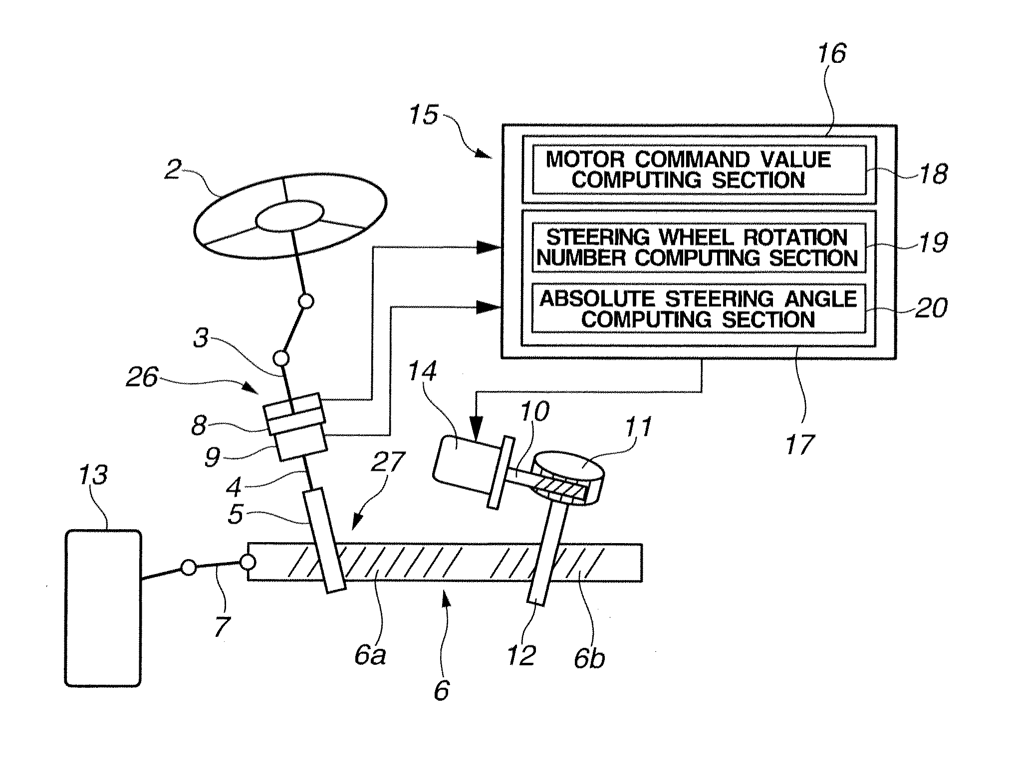
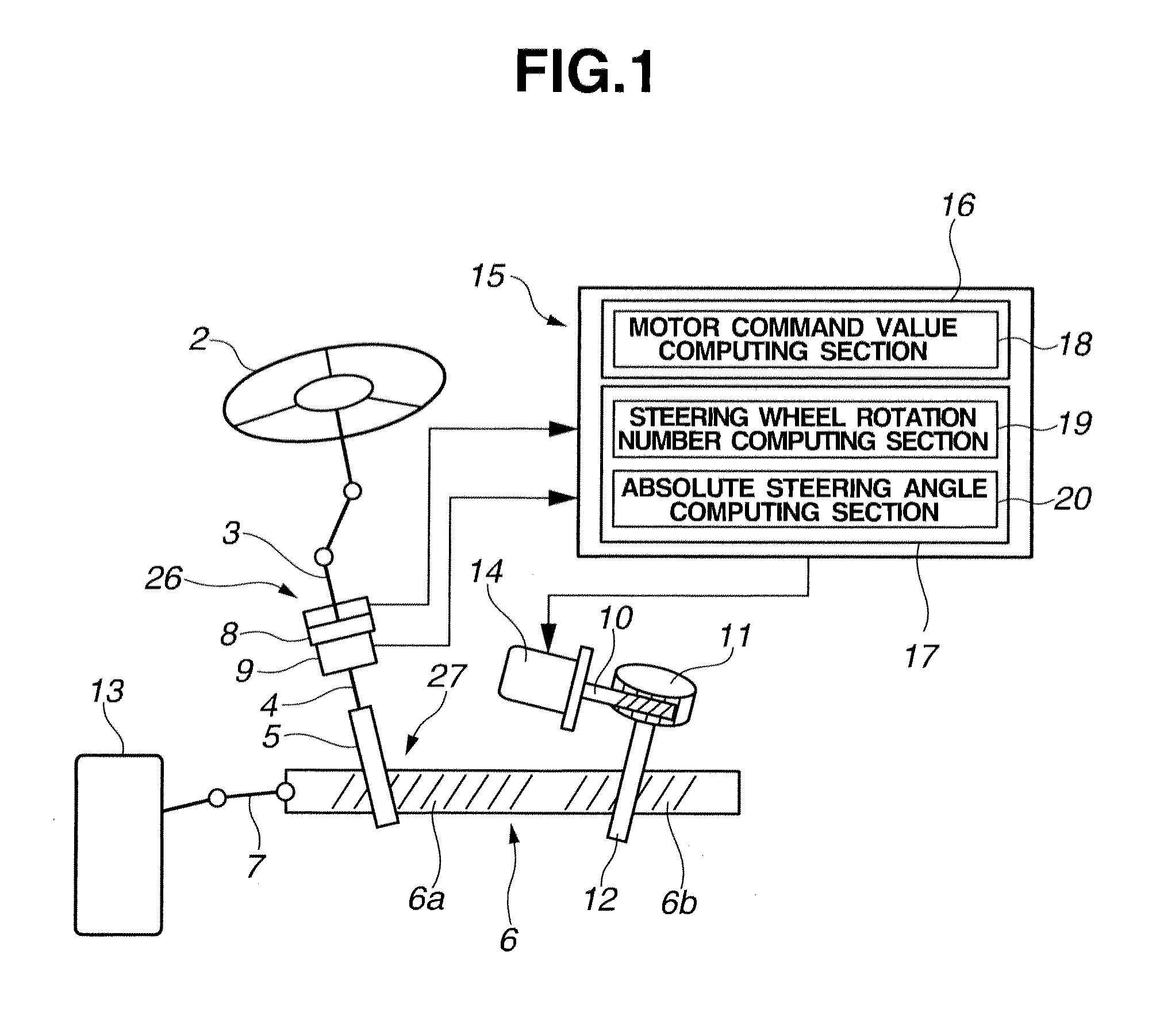
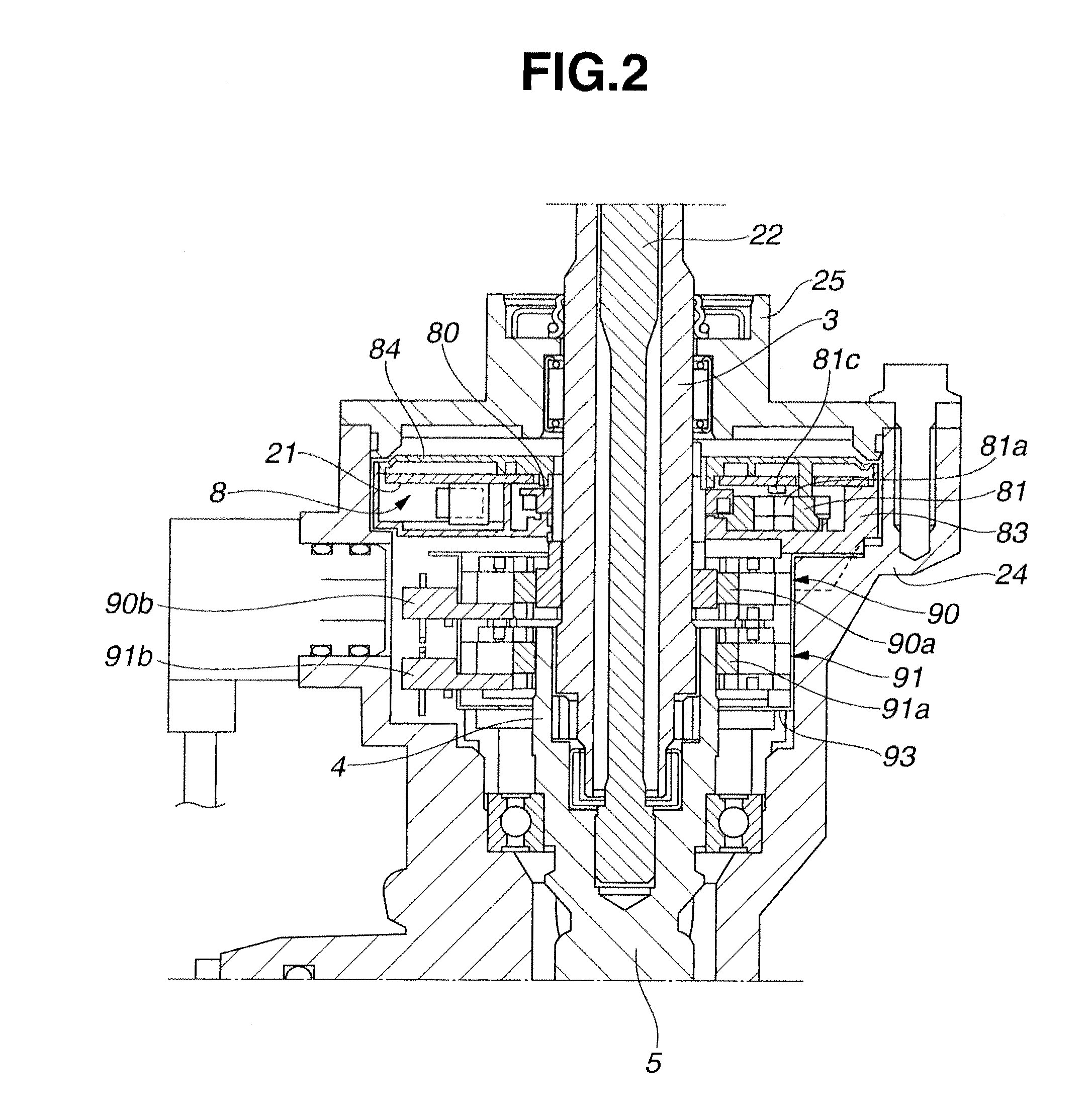
[0045]Referring to FIG. 1, a power steering apparatus for a vehicle to which a steering angle sensor according to a first embodiment of the present invention is applied is explained. FIG. 1 is a schematic diagram of power steering apparatus 1. As shown in FIG. 1, power steering apparatus 1 includes steering wheel 2, steering shaft 3 connected to steering wheel 2, output shaft 4 connected to steering shaft 3, first pinion shaft 5 connected to output shaft 4, rack bar 6 engaged with first pinion shaft 5, tie rod 7 connected to an end portion of rack bar 6, and steerable road wheel 13 connected to tie rod 7. First rack teeth 6a are formed in a portion of rack bar 6 which is engaged with pinion shaft 5. Torsion bar 22 is disposed between steering shaft 3 and output shaft 4 (see FIG. 2). Steering shaft 3 and output shaft 4 are constructed so as to be rotatable relative to each other in a range of torsional motion of torsion bar 22. Power steering a...

second embodiment

[0083]Referring to FIG. 11 and FIG. 12, a steering angle sensor according to a second embodiment of the present invention is explained. The second embodiment differs from the first embodiment in that main gear 80 is biased by leaf spring 87. Like reference numerals denote like parts, and therefore, detailed explanations therefor is omitted.

[0084]FIG. 11 is a perspective view of steering angle sensor 8 according to the second embodiment of the present invention. FIG. 12 is a diagram of steering angle sensor 8 according to the second embodiment of the present invention as viewed in the axial direction of steering shaft 3. Steering angle sensor 8 according to the second embodiment includes main gear accommodating portion 83c of steering angle sensor housing 83 in which main gear 80 is accommodated, and two engaging grooves 83b formed in a peripheral side wall of main gear accommodating portion 83c. Engaging grooves 83b are cutout portions spaced apart from each other in a circumferenti...

third embodiment

[0088]Referring to FIG. 13 and FIG. 14, a steering angle sensor according to a third embodiment of the present invention is explained. The third embodiment differs from the first embodiment in that main gear 80 in biased by spring portion 88 formed integrally with steering angle sensor housing 83. Like reference numerals denote like parts, and therefore, detailed explanations therefor is omitted.

[0089]FIG. 13 is a diagram of steering angle sensor 8 according to toe third embodiment of the present invention before mounting main gear 80 to steering angle sensor housing 63 as viewed from one side in the axial direction of steering shaft 3. FIG. 14 is a diagram of steering angle sensor 8 according to the third embodiment of the present invention after mounting main gear 80 to steering angle sensor housing 83 as viewed from an opposite side in the axial direction of steering shaft 3.

[0090]In steering angle sensor 8 according to the third embodiment, steering angle sensor housing 83 is fo...


PUM


Abstract

A steering angle sensor for a vehicle including a steering angle sensor housing, a first gear, a rotation transmitting portion, a second gear meshing with the first gear, a third gear meshing with the first gear or the second gear, first and second magnetoresistance effect elements to detect first and second rotation angles as rotation angles of the second and third gears, respectively, and a biasing member disposed in the steering angle sensor housing to bias the first gear toward the second gear, wherein the first and rotation angles are combined to determine an absolute steering angle indicative of an amount of rotation of a steering wheel when the steering wheel is rotated from a neutral position in which a steerable road wheel is oriented to a straight ahead direction of the vehicle.

Description

BACKGROUND OF THE INVENTION[0001]The present invention relates to a steering angle sensor.[0002]Japanese Patent Application Unexamined Publication No. P2001-505667 discloses a steering angle sensor including a gear (hereinafter referred to as a first gear) mounted on a steering shaft to make a unitary rotation therewith and two gears (hereinafter referred to as a second gear and a third gear) meshing with the first gear. The second and third gears are respectively equipped with magnets, and have numbers of teeth different from each other. The steering angle sensor can detect a rotation angle not less than 360 degrees on the basis of a difference between rotation angles of the second gear and the third gear which is generated because of the different numbers of teeth.SUMMARY OF THE INVENTION[0003]However, in the steering angle sensor of the above-described conventional art, there is such a fear that an error in detection of the rotation angle of the steering shaft is caused due to ba...

Claims


Application Information

Patent Timeline
IPC IPC(8): B62D1/04G01B5/24
CPCG01B5/24B62D1/04B62D15/0215B62D15/0245Y10T74/20834B62D5/04
Inventor TAKAYANAGI, NAOKIMARUYAMA, TATSUYOSHISHIRAKUBO, KIYOTAKASHIINO, KOHTARO
Owner HITACHI ASTEMO LTD
Why Eureka
Try Eureka