Electric heating device

Active Publication Date: 2014-07-31
TOYOTA JIDOSHA KK
View PDF3 Cites 7 Cited by
  • Summary
  • Abstract
  • Description
  • Claims
  • Application Information

AI Technical Summary

Benefits of technology

[0013]The present invention makes it possible to uniformly apply an e

Problems solved by technology

When the electrode abrades, the abraded part of the electrode does not closely come in contact with the workpiece, which makes it impossible to uniformly apply an electric current to the workpiece.
Moreover,

Method used


Image

  • Electric heating device
  • Electric heating device
  • Electric heating device

Examples


Embodiment Construction

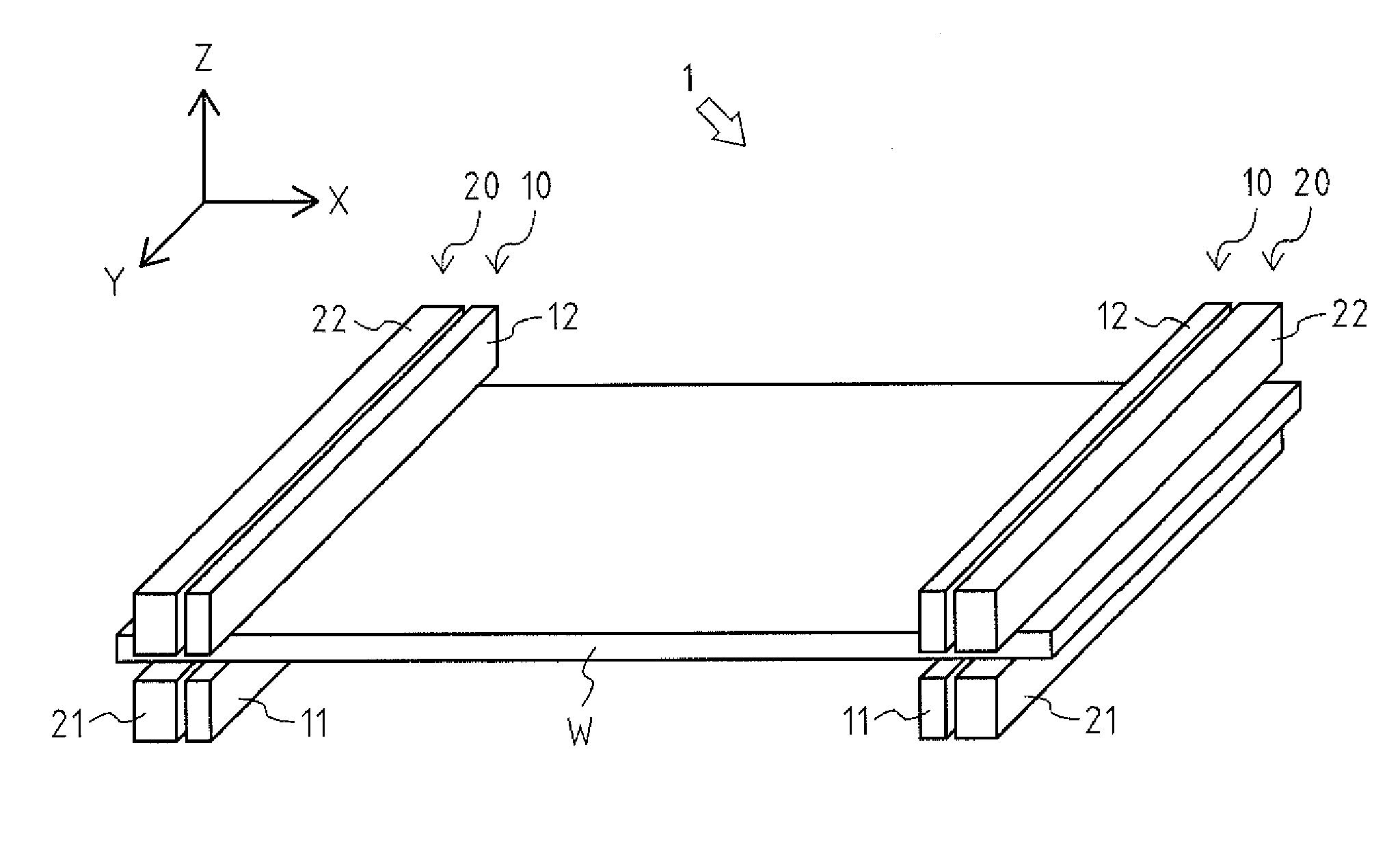
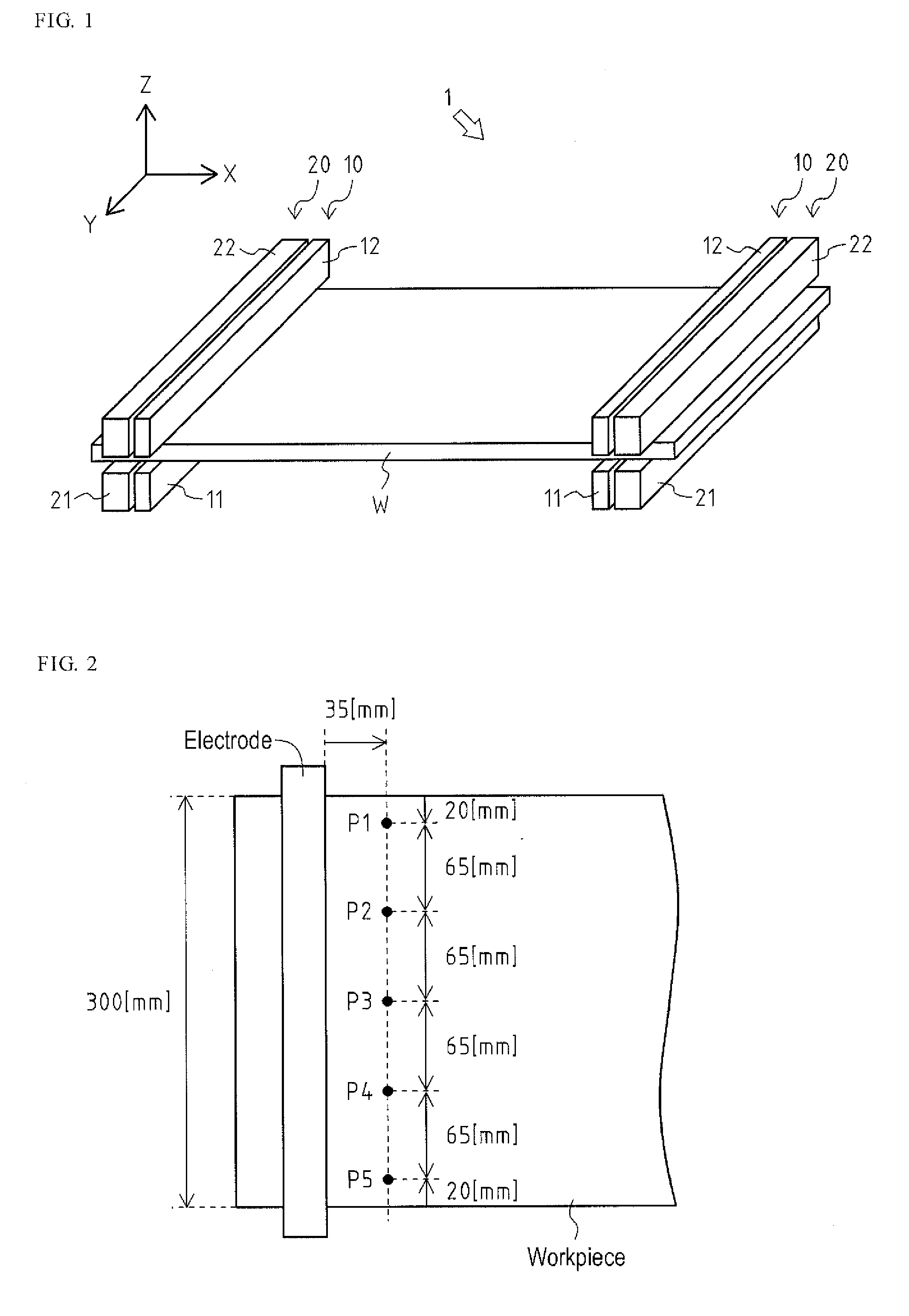
[0022]With reference to FIG. 1, described below is an electric heating device 1 as an embodiment of an electric heating device according to the present invention.

[0023]The electric heating device I applies an electric current to a workpiece W to heat the workpiece W.

[0024]For convenience, it is assumed that an arrow X in FIG. 1 indicates a right direction of the workpiece W to define a right-left direction. Moreover, it is assumed that an arrow Y in FIG. 1 indicates a front direction of the workpiece W to define a front-rear direction. Additionally, it is assumed that an arrow Z in FIG. 1 indicates a top direction of the workpiece W to define a top-bottom direction.

[0025]As shown in FIG. 1, the workpiece W is a rectangular flat plate whose longitudinal direction corresponds to the right-left direction, and both the surfaces thereof face in the top-bottom direction. The workpiece W is to be heated by the electric heating device 1, and is made of a conductive material such as a steel ...


PUM

PropertyMeasurementUnit
Lengthaaaaaaaaaa
Lengthaaaaaaaaaa
Pressureaaaaaaaaaa

Abstract

Disclosed is an electric heating device capable of uniformly applying an electric current to a workpiece without causing abrasion of electrodes. An electric heating device includes a pair of electrodes for applying an electric current to a workpiece, and a pair of clamps for fixing the workpiece. The electrode extends along the surface of the workpiece in a direction perpendicular to an electric current direction while maintaining a constant length in the electric current direction, and sandwiches the workpiece therein. The clamp is arranged in the vicinity of the electrode, and sandwiches a part of the workpiece other than a part to be heated therein. A pressure at which the clamp sandwiches the workpiece therein is higher than a pressure at which the electrode sandwiches the workpiece therein.

Description

TECHNICAL FIELD[0001]The present invention relates to an electric heating device for applying an electric current to a flat plate-like workpiece to heat the workpiece.BACKGROUND ART[0002]Conventionally, a hot-press forming is publicly known in which, after heating a workpiece, such as a steel plate, to above a temperature at which an austenite structure appears therein, cooled dies press and quench the workpiece at the same time.[0003]In the above-mentioned hot-press forming, electric heating is widely known as a technique for heating the workpiece (for example, see Patent Literature 1).[0004]The electric heating is a technique for heating the workpiece by utilizing Joule heat generated by applying an electric current to the workpiece with at least one pair of electrodes attached to the workpiece.[0005]In the electric heating, the heated workpiece thermally expands, and deforms. Therefore, it is necessary to control the deformation of the workpiece to a minimum by bringing the elect...

Claims


Application Information

Patent Timeline
IPC IPC(8): C21D1/40H05B3/00
CPCH05B3/0023C21D1/40C21D9/46H05B3/0004H05B2203/016
Inventor MATSUMOTO, SHIN'ICHIROH
Owner TOYOTA JIDOSHA KK
Why Eureka
Try Eureka