Box Structures for Carrying Loads and Methods of Making the Same

a box structure and load technology, applied in the field of box structure for carrying loads and methods of making the same, can solve the problems of increasing the fuel required for a given flight profile, reducing the performance of the aircraft, and increasing manufacturing costs

Active Publication Date: 2014-07-31
THE BOEING CO
View PDF16 Cites 36 Cited by
  • Summary
  • Abstract
  • Description
  • Claims
  • Application Information

AI Technical Summary

Problems solved by technology

The fabrication process may involve extensive time and manual labor to assemble a large number of component parts, and this may result in increased manufacturing costs.
However, the use of numerous heavy fasteners may add weight to the aircraft, which, in turn, may decrease the aircraft's performance and may result in increased fuel required for a given flight profile.
This increased fuel requirement may, in turn, result in increased fuel costs.
In addition, such fasteners may require additional fuel tight sealing which may increase the fabrication time, labor and cost, and which, in turn, may increase the overall manufacturing and operation costs.
Further, the use of numerous fasteners made of metal installed through the outer composite wing skin panels may result in an increased risk of a lightning strike to the wing.
However, such approach may compromise the efficiency of those composite components and may significantly increase part count in the ribs and fastener attachments in order to maintain stability of the composite aircraft transport wing and stabilizer box structure.

Method used


Image

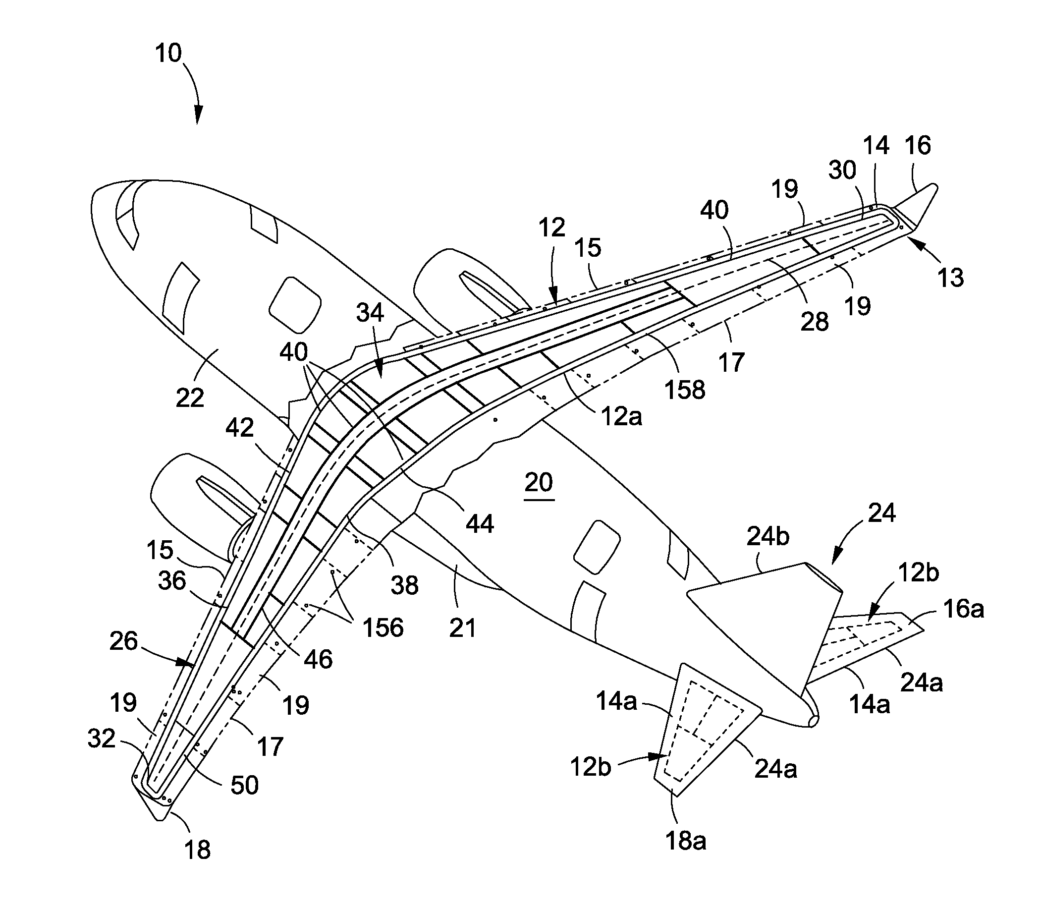
  • Box Structures for Carrying Loads and Methods of Making the Same
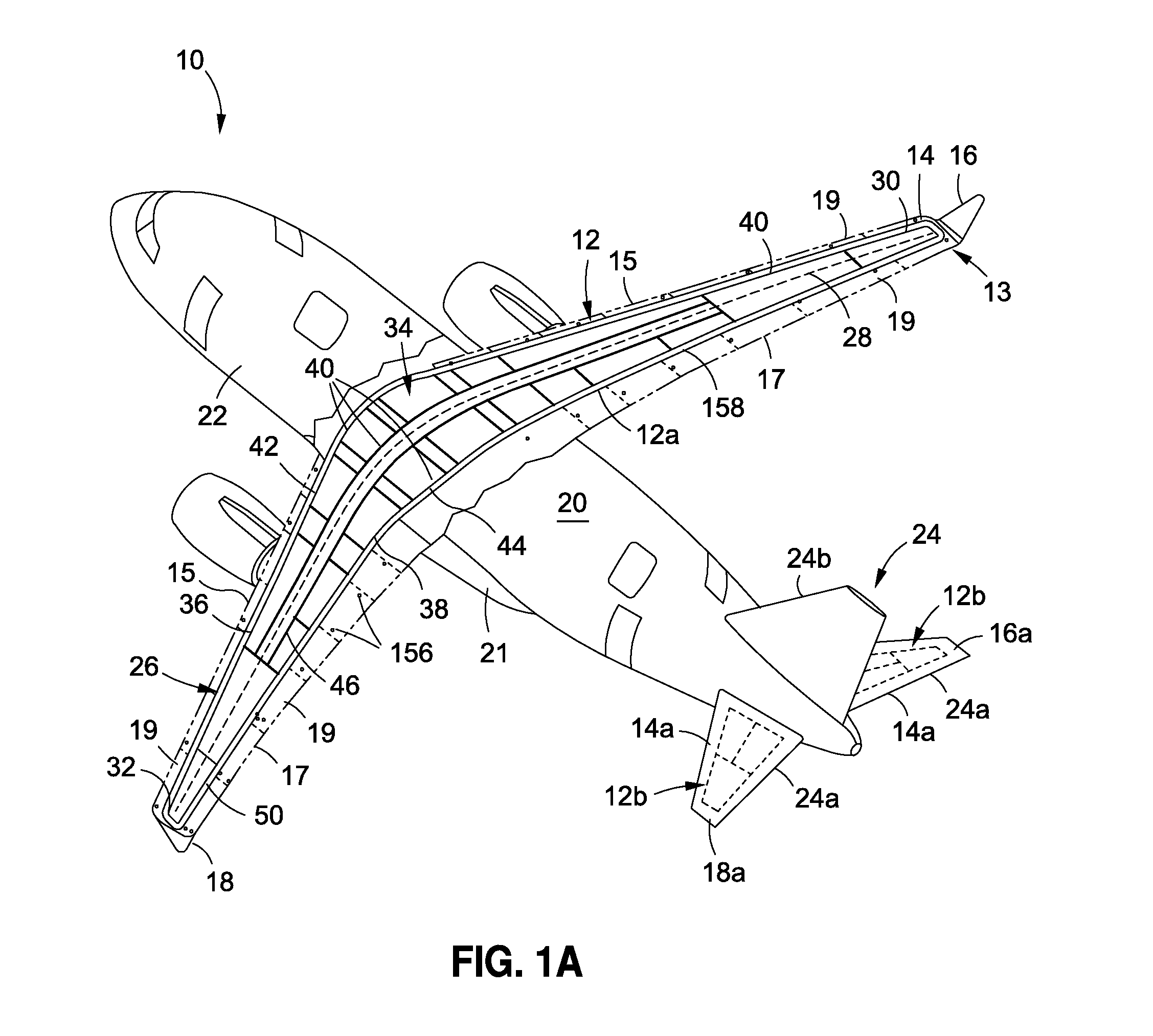
  • Box Structures for Carrying Loads and Methods of Making the Same
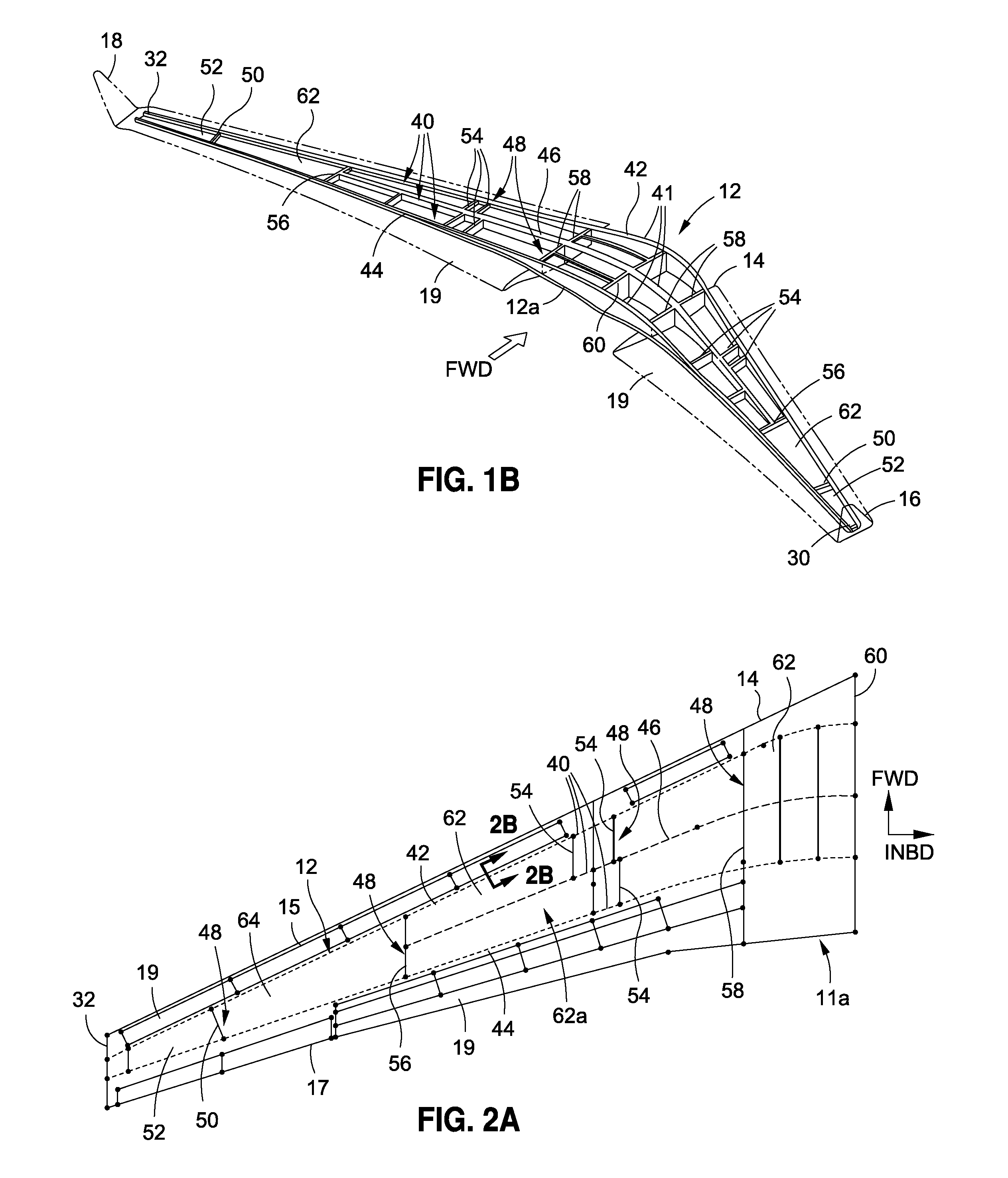
  • Box Structures for Carrying Loads and Methods of Making the Same

Examples


first embodiment

[0055]FIG. 4 is an illustration of a partial sectional view of a spar closeout joint 130a of the disclosure. FIG. 4 shows the dense pack 80, the outer facesheet 72, the inner facesheet 74, and the core portions 66. FIG. 4 further shows a filler portion 128, such as a soft laminate, of the spar 40 with a first spar closeout attach angle 106a and a second spar closeout attach angle 106b. The spar closeout joint 130a shown in FIG. 4 is located at an inner portion 132 and joins the filler portion 128 of the spar 40 to the dense pack 80 at a bond line 134 along the inner facesheet 74. The spar closeout joint 130a uses a separate angle 136 to act as a forward location stop for the filler portion 128 of the spar 40 during assembly. This embodiment may have the advantageous feature of allowing for the spar 40 to be self-locating.

second embodiment

[0056]FIG. 5 is an illustration of a partial sectional view of a spar closeout joint 130b of the disclosure. FIG. 5 shows the dense pack 80, the outer facesheet 72, the inner facesheet 74, and the core portions 66. FIG. 5 further shows the filler portion 128, such as a soft laminate, of the spar 40, where the spar 40 is in the form of intermediate spar 46. FIG. 5 further shows the first spar closeout attach angle 106a and the second spar closeout attach angle 106b. The spar closeout joint 130b shown in FIG. 5 is attached at a center portion 138 on the dense pack 80. This embodiment may have the advantageous feature of centering the filler portion 128 of the spar 40 on the dense pack 80 which may reduce reaction loads in the outer facesheet 72 and the inner facesheet 74 due to any out of plane movement of the dense pack 80.

third embodiment

[0057]FIG. 6 is an illustration of a partial sectional view of a spar closeout joint 130c of the disclosure. FIG. 6 shows the dense pack 80 split into dense pack sections 80a, 80b and shows the outer facesheet 72, the inner facesheet 74, and the core portion 66. FIG. 6 further shows the filler portion 128, such as a soft laminate, of the spar 40 having a square edge 142 and having a sandwich configuration comprising a first spar facesheet 100 and a second spar facesheet 102. The spar closeout joint 130c shown in FIG. 6 is a split dense pack type and has the first spar closeout attach angle 106a and the second spar closeout attach angle 106b contained within the dense pack 108 at dense pack portions 140a, 140b, respectively. In addition, the first spar closeout attach angle 106a and the second spar closeout attach angle 106b may be tapered and need not be a full length. Preferably, the first spar closeout attach angle 106a is as close to the inner facesheet 74 as possible. This embod...


PUM

PropertyMeasurementUnit
anglesaaaaaaaaaa
anglesaaaaaaaaaa
box structureaaaaaaaaaa

Abstract

There is provided a box structure for carrying load having upper and lower composite integrated sandwich panels. The panels have facesheets sandwiching one or more core portions and adjacent dense packs oriented in an axial direction. The box structure further has a plurality of spars. Each spar has a web and web attachments and has a spar length in the axial direction. The plurality of spars are connected to the panels with the web attachments located at the dense packs. The facesheets are configured to carry primarily torsion and pressure loads in shear and no significant axial loads. The dense packs are configured to carry all significant box bending in axial tension and compression loads.

Description

BACKGROUND[0001]1) Field of the Disclosure[0002]The disclosure relates generally to box structures for carrying loads and methods for making the same, and more particularly, to composite bonded box structures for vehicles and architectural structures, and methods of making the same.[0003]2) Description of Related Art[0004]Composite structures, such as carbon fiber-reinforced plastic (CFRP) composite structures, are used in a wide variety of applications, including in the manufacture of aircraft, spacecraft, rotorcraft, automobiles, watercraft, and other vehicles and structures, due to their high strength-to-weight ratios, corrosion resistance, and other favorable properties. For example, in aircraft construction, composite structures are used in increasing quantities to form the wings, tail sections, fuselage, and other components.[0005]Existing composite aircraft transport wing and stabilizer box structures may utilize integrally stiffened panel structures consisting of outer compo...

Claims


Application Information

Patent Timeline
Patent Type & Authority Applications(United States)
IPC IPC(8): B64C3/18B64F5/00
CPCB64F5/0009B64C3/185B29D99/0014B29C70/30B64C3/20B32B5/022B32B5/024B32B5/12B32B5/18B32B3/12B32B2260/023B32B2260/046B32B2262/0261B32B2262/0269B32B2262/101B32B2262/106B32B2266/08B32B2307/54B32B2307/542B32B2307/718B32B2605/18Y02E10/72Y02T50/40E05B63/22E05C1/16
Inventor MARCOE, JEFFERY L.NORDMAN, PAUL S.BROWN, STEPHEN T.ROESELER, WILLIAM G.ISOMURA, TERRY K.WESTRE, WILLARD N.
Owner THE BOEING CO
Why Eureka
Try Eureka