Vibration isolator with coil spring

a technology of vibration isolator and coil spring, which is applied in the field of vibration isolators, can solve the problems of spring not acting, horizontal force, horizontal shift of anti-vibration mounted load, etc., and achieve the effects of avoiding horizontal stiffness reduction, easy vertical adaptation, and increasing the stiffness of the vibration isolator

Active Publication Date: 2014-07-31
INTEGRATED DYNAMICS ENG
View PDF14 Cites 8 Cited by
  • Summary
  • Abstract
  • Description
  • Claims
  • Application Information

AI Technical Summary

Benefits of technology

[0042]By adjusting the stiffness the natural frequency of the individual vibration isolators may in particular be adapted in a manner so that all vibration isolators exhibit substantially the same natural frequency. Different natural frequencies of the individual isolators should be avoided, as this may cause a swaying movement of the load to be isolated. If now the load on one vibration isolator is greater, for example because of a non-symmetrical center of gravity, the stiffness of that vibration isolator may be increased correspondingly to match the natural frequency thereof to that of the other vibration isolators.
[0043]Furthermore, the leaf spring permits to very easily adapt the vertical stiffness to the respective installation place without that the coil spring needs to be replaced.
[0044]Preferably, in the horizontal direction, the coil spring is rigidly connected to the base or to the load to be isolated by means of at least two leaf springs that are spaced from each other. In this manner, tilting and thus a possible reduction of horizontal stiffness is avoided.

Problems solved by technology

This is necessary because in the region of load limit a mechanical spring does no longer behave linearly and can be damaged.
However, it has now been found that during mechanical height adjustment torques may be generated in the mechanical spring system, which may result in a horizontal force.
This horizontal force component usually leads to a horizontal shift of the anti-vibration mounted load, which is undesirable.
In active vibration isolation systems, a horizontal shift is particularly disadvantageous, since the opposite components of non-contact actuators will be offset thereby relative to one another.
In case of a Lorentz coil, for example, this may result in that the plunger coil touches the permanent magnet, or it will at least result in that the size of the air gap between the plunger coil and the permanent magnet is no longer in the desired range.
Thus, after height adjustment the vibration isolation system additionally has to be adjusted in the horizontal direction, which is cumbersome.

Method used


Image

  • Vibration isolator with coil spring
  • Vibration isolator with coil spring
  • Vibration isolator with coil spring

Examples


Embodiment Construction

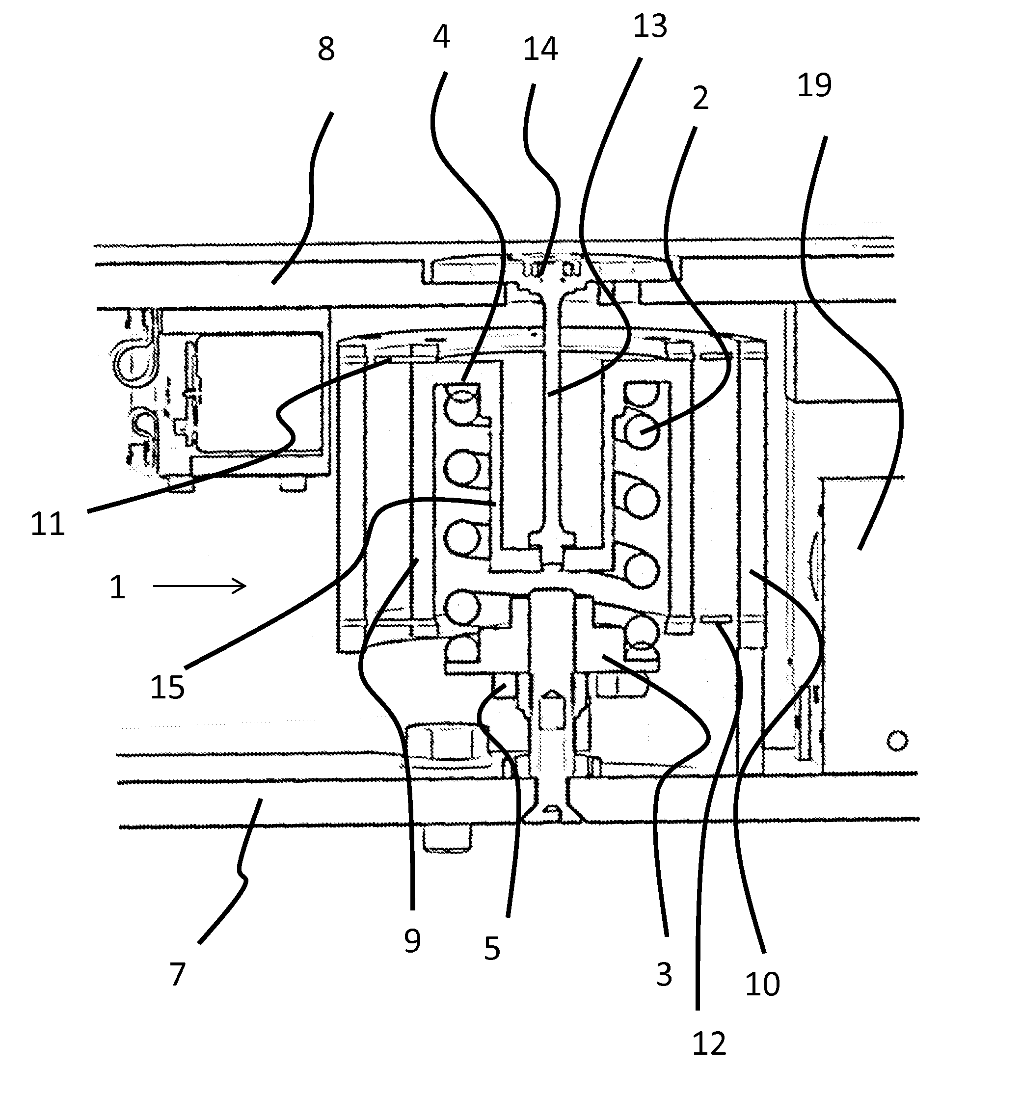
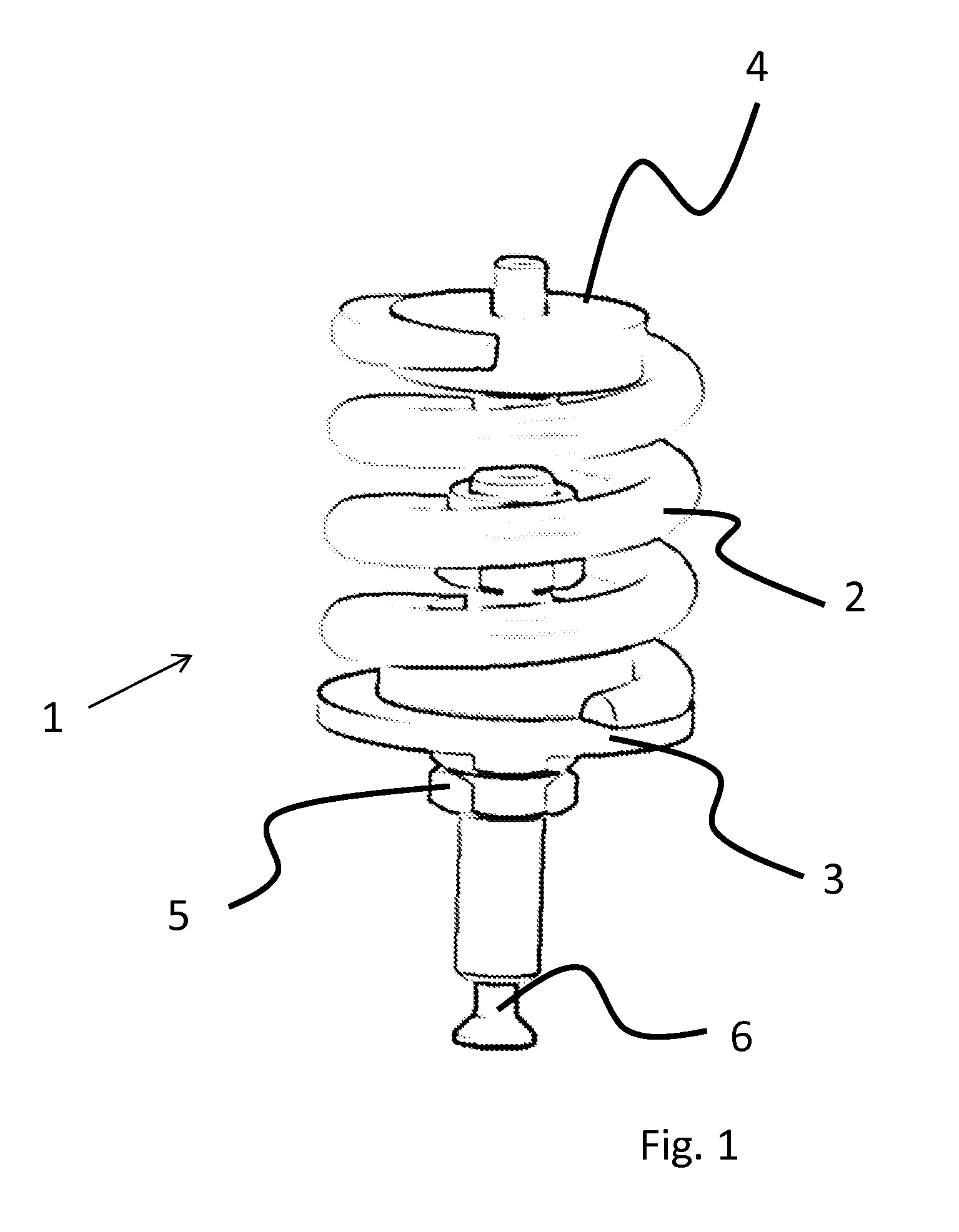
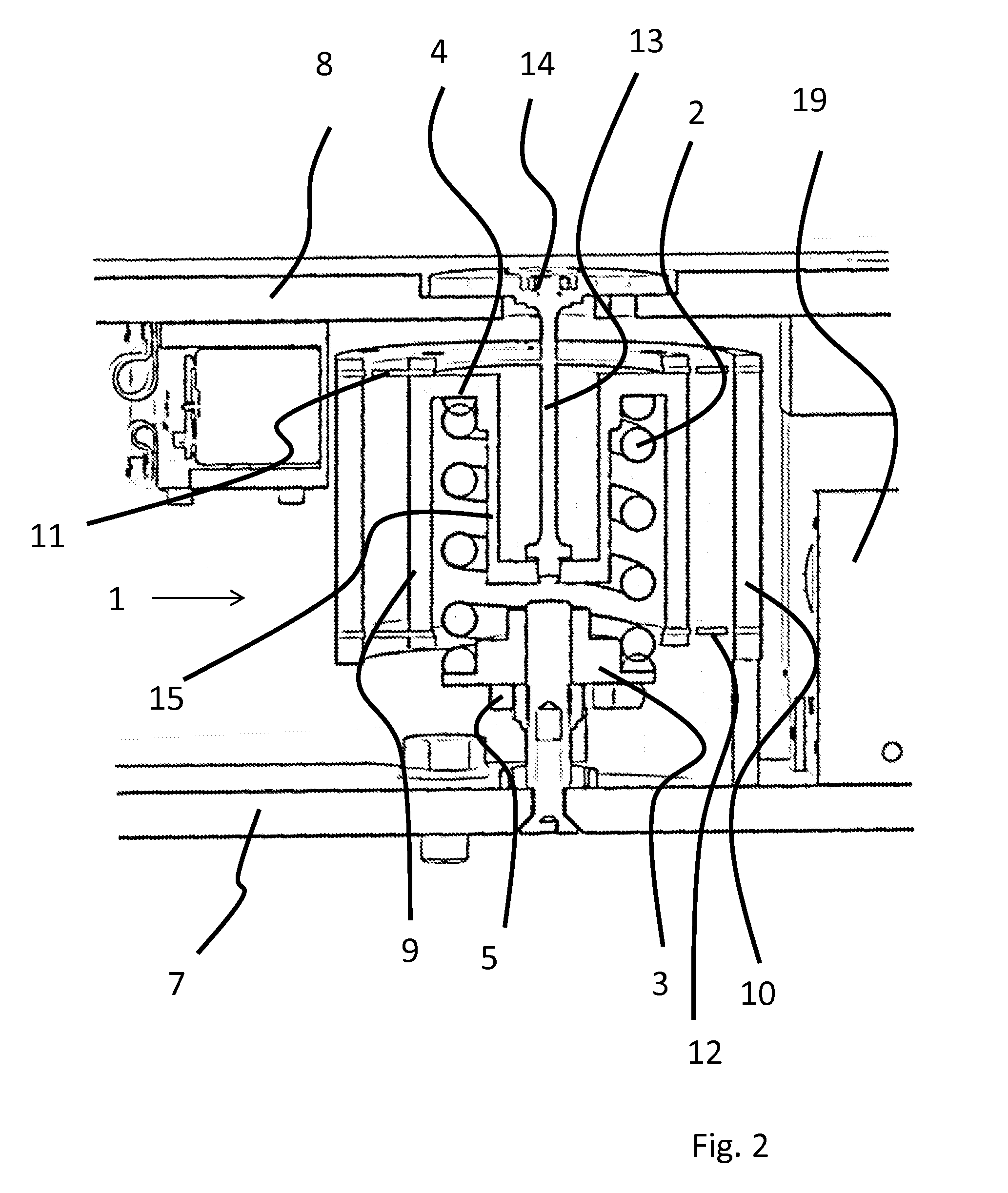
[0058]The invention will now be described in more detail with reference to an exemplary embodiment schematically illustrated in the drawings of FIGS. 1 to 5.

[0059]FIG. 1 schematically illustrates the essential components of a vibration isolator 1 which comprises a coil spring 2.

[0060]Coil spring 2 is connected to a lower spring plate 3 and to an upper spring plate 4 and in this manner, through the spring plates, it may be attached to the anti-vibration mounted load (not shown) and to the base (not shown).

[0061]Lower spring plate 3 is adjustable in the vertical direction by means of an adjusting element 5 which is configured as a nut arranged on a threaded rod in this exemplary embodiment. Using a fastening member 6 which is configured as a screw in this exemplary embodiment, lower spring plate 3 is secured to the base.

[0062]The anti-vibration mounted load is connected to the base through coil spring 2.

[0063]It will be understood that in this way, in the installed state, vibration is...


PUM


Abstract

The invention relates to a vibration isolator that includes a coil spring. In a horizontal direction, the coil spring is rigidly connected to the base or to the load to be isolated.

Description

CROSS-REFERENCE TO RELATED APPLICATIONS[0001]European Patent Application No. 13 153 154.3, with a filing date of Jan. 29, 2013, is incorporated herein by reference.FIELD OF THE INVENTION[0002]The invention relates to a vibration isolator that includes a coil spring, and to a vibration isolation system. More particularly the invention relates to a vibration isolation system which is used for vibration-isolated mounting of machines, in particular in the field of semiconductor industry.BACKGROUND OF THE INVENTION[0003]Vibration isolation systems which include a coil spring, mostly in form of a steel spring, are known. In such a system a load to be isolated from the ground is mounted on three or more vibration isolators which include a coil spring that is effective at least in a vertical direction.[0004]Such coil springs provide for passive vibration isolation in a very simple way, in particular even for quite heavy components.[0005]Above the natural frequency of the spring-mass system,...

Claims


Application Information

Patent Timeline
Patent Type & Authority Applications(United States)
IPC IPC(8): F16F15/067F16F15/04
CPCF16F15/063F16F1/121F16F1/128F16F3/02F16F15/067F16F15/046F16F15/03
Inventor EVERS, ARNDT
Owner INTEGRATED DYNAMICS ENG
Why Eureka
Try Eureka