Eureka AIR delivers breakthrough ideas for toughest innovation challenges, trusted by R&D personnel around the world.

Cistern Assembly

Inactive Publication Date: 2014-08-07
METAFLUSH
View PDF1 Cites 0 Cited by
  • Summary
  • Abstract
  • Description
  • Claims
  • Application Information

AI Technical Summary

Benefits of technology

The patent describes a device with two sections that allow fluid to flow through it. The device also has magnetic components that interact with each other to cause the device to pivot. This helps to increase the fluid flow through the device.

Problems solved by technology

The cistern outlet valve in conventional systems is prone to wear and damage resulting in ineffective sealing and consequent leaking and loss of water to the sewerage system.
This results in the need for additional parts and increased complexity and cost.
In one version the operating knob protrudes from the front of the cistern which may cause inconvenience.
Furthermore, the requirement for a protruding operating knob does not lend the cistern to application in a concealed (in wall) unit.

Method used


Image

  • Cistern Assembly
  • Cistern Assembly
  • Cistern Assembly

Examples


second embodiment

[0143]With reference to FIGS. 3A-3D there is shown a cistern assembly 30 comprising a basin forming a cistern member 31 in a cistern housing 12 and actuation means (not shown). The cistern assembly 30 is similar to that described for cistern assembly 10, except that the basin forming the cistern member 31 has a substantially flat or substantially convex portion that is substantially symmetrical about the vertical axis of the cistern member.

[0144]FIG. 3A shows the base wall32 of the basin forming the cistern member 31 is flattened and is symmetrically positioned about the vertical axis of the cistern member.

[0145]FIG. 3B shows the base wall 33 of the basin forming the cistern member 31 forming an inwardly protruding V-shape symmetrically positioned about the vertical axis of the cistern member.

[0146]FIG. 3C shows the base wall 34 of the basin forming the cistern member 31 forming an inwardly protruding ramp shape symmetrically positioned about the vertical axis of the cistern member....

third embodiment

[0151]FIGS. 5A, 5B, 6A and 6B illustrate a basin forming a cistern member 41. FIGS. 5A and 5B show a basin forming a cistern member 41. Cistern member 41 is intended for use with a cistern housing and actuation means (not shown) to form a cistern assembly 40 according to the present invention. The cistern member 41 is similar to cistern member 11, except that the basin forming the cistern member 41 has a substantially wedge shaped recess section 42 located in the back wall or in the front wall, or in both the back wall and front wall, of the basin of the cistern member 41. The, or each, wedge shaped recess 42 is substantially symmetrical about the vertical axis of symmetry 29 of the cistern member 41 when the cistern member is in the equilibrium position. The, or each, wedge shaped recess 42 has an apex 43 to provide a recessed pivot point for the cistern member 41 to rest on in the cistern housing.

[0152]Because the front to back dimension of the cistern member 41 is smaller behind ...

fourth embodiment

[0153]With reference to FIG. 7, there is shown the present invention. FIG. 7 shows a cistern assembly 50 comprising a basin forming a cistern member 11 in a cistern housing 12 and magnetic actuation means 52-56. The cistern assembly 50 is similar to that described in cistern assembly 10, but the pivoting is initiated by magnetic actuation means provided by an arrangement of permanent magnets 52-56 associated with the cistern housing 12 and the cistern member 11.

[0154]The partial cross sectional views in FIGS. 8A-8E show the upper section of a cistern assembly 60 representing further embodiments of the present invention. Cistern assembly 60 comprises a cistern housing 12, and magnetic actuation means and a basin forming a cistern member 61. The basin forming the cistern member 61 is similar to any of those described in the above-mentioned Figures. In one embodiment the cistern member 61 is similar to that described by cistern member 11 in FIG. 1. In further embodiments the cistern me...


PUM


Abstract

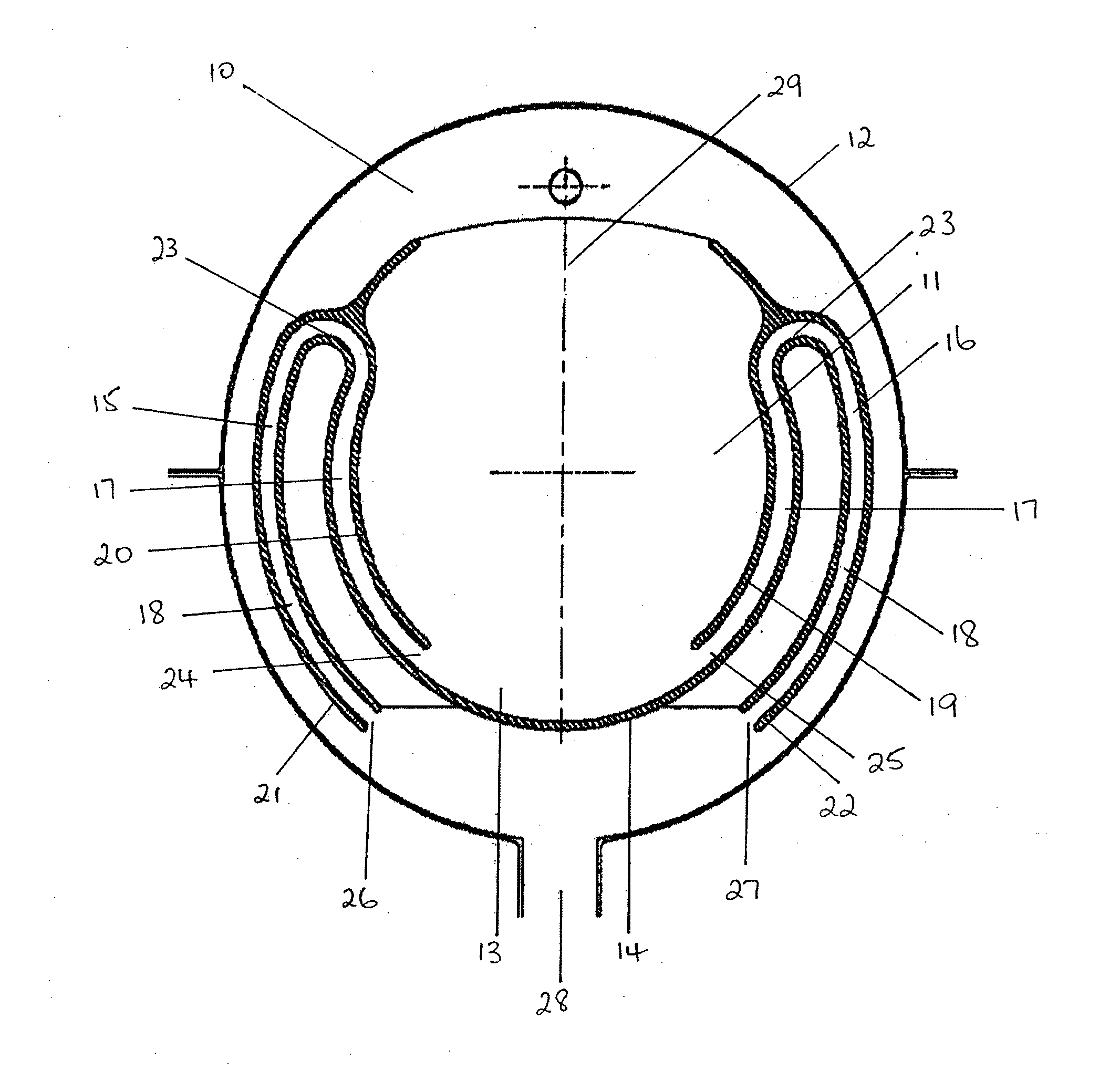
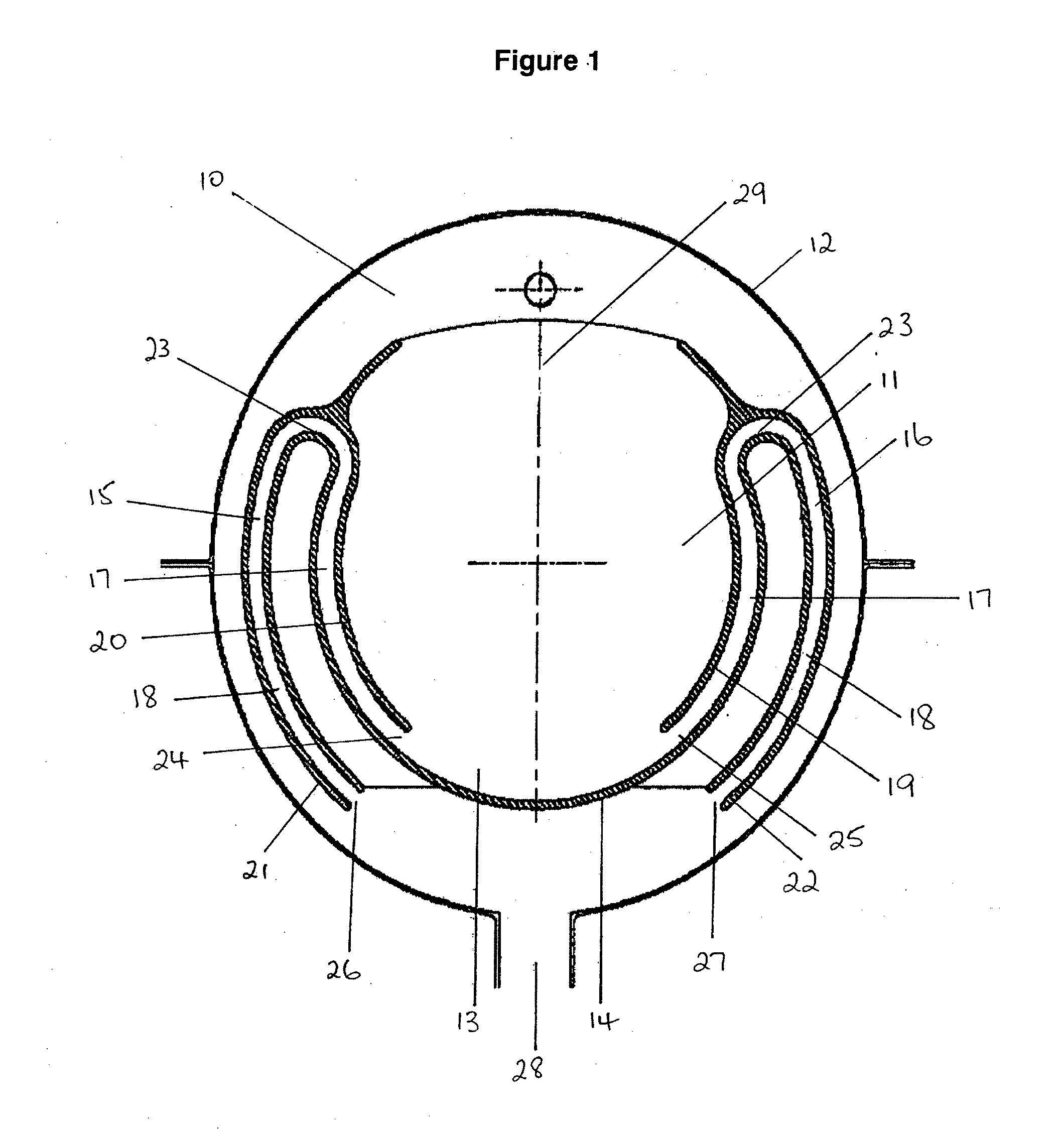
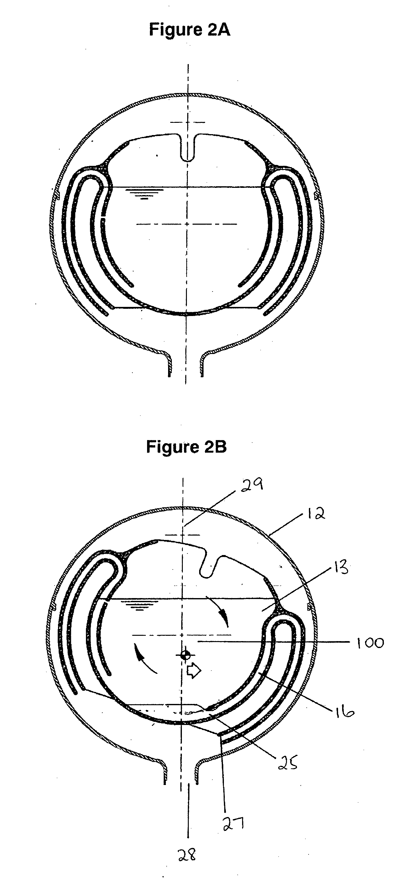
The current invention is directed to a cistern assembly for a flush toilet where the cistern assembly includes a cistern housing including a cistern lid and a cistern base, a cistern member pivotally attached within the cistern housing, and an actuator means associated with the cistern member to pivot the cistern member relative to the cistern housing to discharge the stored water. The cistern member has a base wall that forms a chamber to store the water and a passageway to discharge the water from the chamber, the passageway has an internal inlet and a cistern outlet and is shaped to siphon water through the passageway. The internal inlet is positioned substantially on or adjacent to the pivot vertical axis of the cistern member when the cistern member is in one of the pivoted positions. The actuator means can tilt the cistern member to actuate discharge of water through the passageway so that when the cistern member is pivoted and the passageway is moved below the water level of the stored water of the chamber, the water is drawn through the passageway to the cistern outlet until air within the chamber enters the passageway preventing further water from being drawn into the passageway.

Description

FIELD OF INVENTION[0001]The present invention relates to a flush toilet and urinal systems. The present invention has particular but not exclusive application to a cistern for a flush toilet.BACKGROUND OF THE INVENTION[0002]A flush toilet system operates by the rapid passage of water from the cistern to the toilet bowl which then passes to the underground sewer pipes. Water is stored in the cistern. Water is released from the cistern with the actuating of the flushing mechanism. Water passes through a cistern outlet into the bowl. In conventional systems, when water has drained from the cistern, the outlet valve reseals about the outlet and water from the mains water supply refills the cistern.[0003]The cistern outlet valve in conventional systems is prone to wear and damage resulting in ineffective sealing and consequent leaking and loss of water to the sewerage system. WO 2009 / 039561 describes a cistern system comprising a cistern housing and an internal cistern member. Flushing r...

Claims


Application Information

Patent Timeline
IPC IPC(8): E03D5/10
CPCE03D5/10E03D1/07E03D1/20
Inventor LAKE, ANTONY
Owner METAFLUSH
Why Eureka
Eureka Blog
Learn More