Bond Strength Testing Apparatus and Method For Using Same

a technology of bond strength and testing apparatus, which is applied in the direction of measuring devices, instruments, using mechanical means, etc., can solve the problems of significant wear and tear of moving parts

Active Publication Date: 2014-08-07
PILKINGTON GROUP LTD
View PDF4 Cites 41 Cited by
  • Summary
  • Abstract
  • Description
  • Claims
  • Application Information

AI Technical Summary

Benefits of technology

[0005]The invention relates to a hand-held apparatus for testing the strength of, for example, an adhesive or solder bond between an item of hardware and a substrate material such as a vehicle window. More particularly, the inventive apparatus includes a housing having an interior hollow chamber containing (1) a force transfer shaft which may extend substantially the length of the housing, (2) a return mechanism, such as one or more resilient springs, preferably enclosing the force transfer shaft, and (3) a ferromagnetic member connected to an end of the force transfer shaft movable at least partially within the hollow chamber. An end cap or second housing portion is connected to one end of the housing and such housing end cap contains a magnet such that the magnet is proximate the ferromagnetic member. Preferably, the end cap or multi-part housing is adjustable so as to be capable of varying the distance between the ferromagnetic member and the permanent magnet, which magnet has a predetermined magnetic pull force. A force application member is attached to an end of the force transfer shaft opposite that to which the ferromagnetic member is attached for engaging a bonded item for testing. A return stop member may optionally b

Problems solved by technology

Known testing devices, however, have been found to have a significant number of moving parts which wear out relatively quickly, and produce erratic resul

Method used


Image

  • Bond Strength Testing Apparatus and Method For Using Same
  • Bond Strength Testing Apparatus and Method For Using Same
  • Bond Strength Testing Apparatus and Method For Using Same

Examples


Embodiment Construction

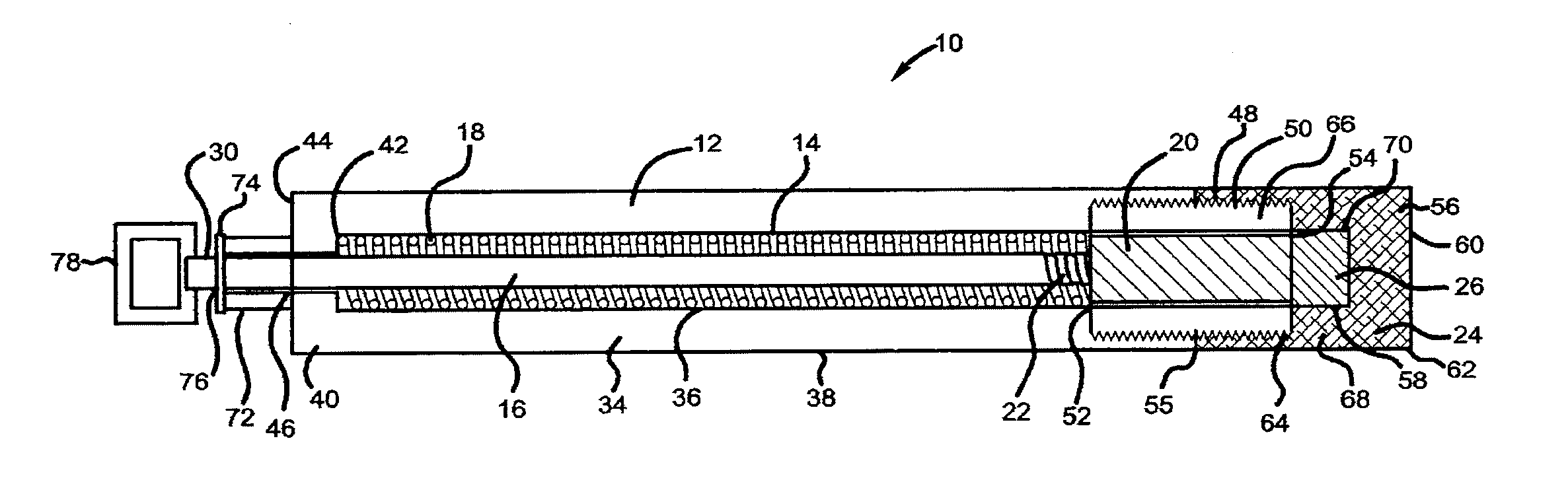
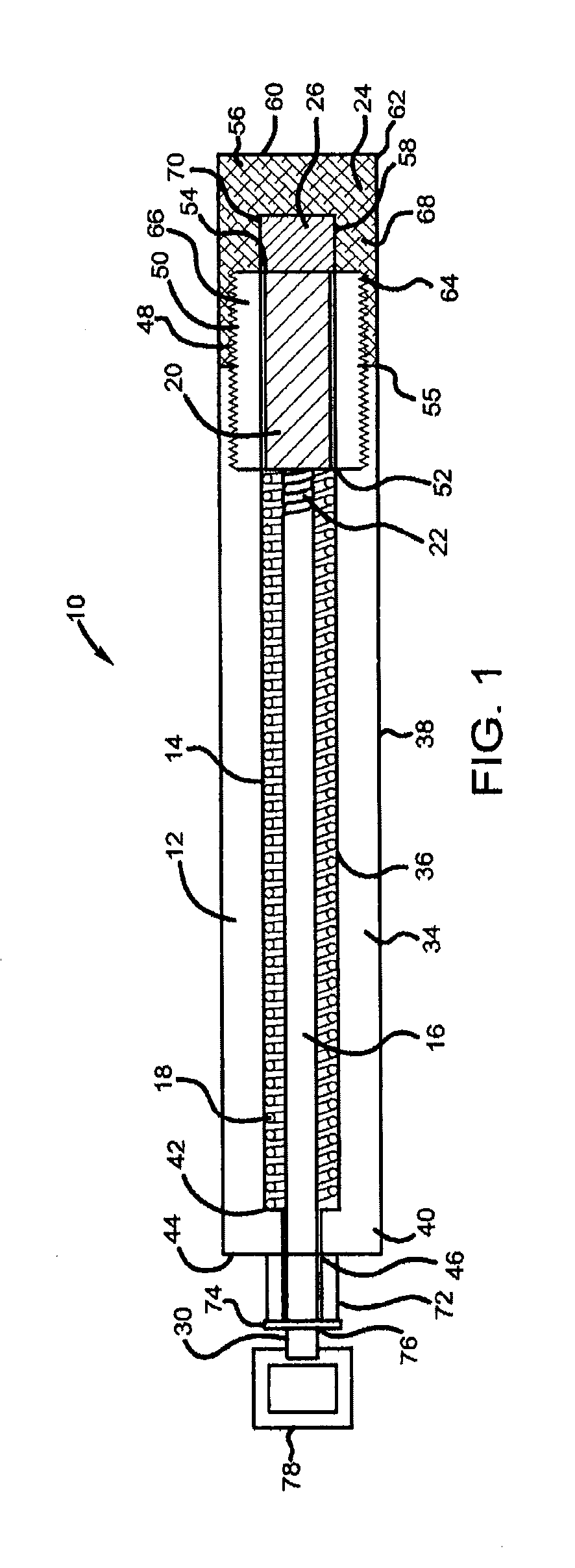
[0015]The invention relates to a hand-held apparatus for testing the strength of, for example, an adhesive or solder bond between an item of hardware and a substrate material such as a glass vehicle window.

[0016]More particularly, in an embodiment the apparatus 10 includes a housing 12 having an interior hollow chamber 14 containing (1) a force transfer shaft 16 extending substantially the length of the housing 12, (2) a return mechanism 18, for example, one or more resilient springs preferably enclosing the force transfer shaft 16 and (3) a ferromagnetic member 20 connected to a second end 22 of the force transfer shaft 16, and movable, at least partially, within the hollow chamber 14. An end cap 24 is connected to one end of the housing 12 and holds a permanent magnet 26 in a position such that the permanent magnet 26 is proximate the ferromagnetic member 20. Preferably, the end cap 24 is adjustable so as to be capable of varying the distance between the ferromagnetic member 20 an...


PUM


Abstract

An apparatus and method tests the strength of a bond between a substrate, especially a vehicle window, and an item bonded thereto. The apparatus includes a force transfer shaft having a first end extending from a housing and a second end positioned within the housing, a ferromagnetic member connected to the end of the force transfer shaft positioned within the housing, and a permanent magnet having a predetermined pull force secured to the housing proximate the ferromagnetic member.

Description

RELATED APPLICATION[0001]This application is claiming the benefit under 35 U.S.C. 119(e), of the provisional application filed Feb. 5, 2013 under 35 U.S.C. 111 (b) which was granted Ser. No. 61 / 760,742. This provisional application is incorporated herein by reference in its entirety.BACKGROUND OF THE INVENTION[0002]The invention relates to an apparatus for testing the strength of a bond between two materials. More particularly, the invention relates to a hand-held apparatus for testing the strength of, for example, an adhesive or solder bond between an item of hardware and a substrate material, especially a vehicle window. A method of using the apparatus is also an aspect of the invention.[0003]Devices for testing the bond strength between two joined materials are known. Known testing devices, however, have been found to have a significant number of moving parts which wear out relatively quickly, and produce erratic results due both to such mechanical wear, as well as to improper us...

Claims


Application Information

Patent Timeline
IPC IPC(8): G01N19/04
CPCG01N19/04
Inventor SITTERLET, CHARLES
Owner PILKINGTON GROUP LTD
Why Eureka
Try Eureka