Striking device with sliding weight for increasing impact force

a technology of sliding weight and striking device, which is applied in the direction of hand hammers, metal-working apparatus, portable percusive tools, etc., can solve the problems of large associated effort which is generally required to swing the known striking device, take a lot of effort to swing, and the operator of such currently known striking device is easily fatigued, so as to facilitate an increase in angular acceleration of the striking device, optimize use and operation, and improve the effect of angular velocity

Inactive Publication Date: 2014-08-07
NEAR TIMOTHY J
View PDF8 Cites 11 Cited by
  • Summary
  • Abstract
  • Description
  • Claims
  • Application Information

AI Technical Summary

Benefits of technology

[0006]A further object of the present invention is to provide a striking device having a weight that slides along the length of the handle away from the hand of the operator using the striking device to the opposite end of the striking device as the striking device is swung. The shift in weight of the striking device enables the person to swing the striking device at a greater angular velocity in comparison to known fixed weight striking devices of the prior art.
[0007]Another object is to provide a striking device having a weight that slides along the length of the striking device such that the shift in weight of the striking device facilitates an increase in angular acceleration of the striking device when the striking device is swung.
[0008]Another object of the invention is to provide a striking device that has interchangeable sliding weights, striking heads and/or handles that are suitable for different tasks (e.g., framing vs. finish carpentry) to optimize use and operation of the striking device.
[0009]The invention generally relates to a striking device which includes handle, which may comprise a frame, to which a striking head is either fixedly attached or form integrally therewith. At least a portion of the handle/frame and the striking head are hollow and form an elongate longitudinal channel. A sliding weight is located within the handle/frame and is slidable along the elongate longitudinal channel between a position that is remote from the head to a position within or located adjacent to the striking head. A low friction slide tube typically extends along the channel and suppo...

Problems solved by technology

Since a majority of the weight, of such currently known striking devices, is typically fixedly located at the head of such striking devices, it take much effort to swing such currently known striking devices and an operator, of such currently known striking devices, generally becomes easily fatig...

Method used


Image

  • Striking device with sliding weight for increasing impact force
  • Striking device with sliding weight for increasing impact force
  • Striking device with sliding weight for increasing impact force

Examples


Embodiment Construction

[0032]The present invention will be understood by reference to the following detailed description, which should be read in conjunction with the appended drawings. It is to be appreciated that the following detailed description of various embodiments is by way of example only and is not meant or intended to limit, in any way, the scope of the present invention.

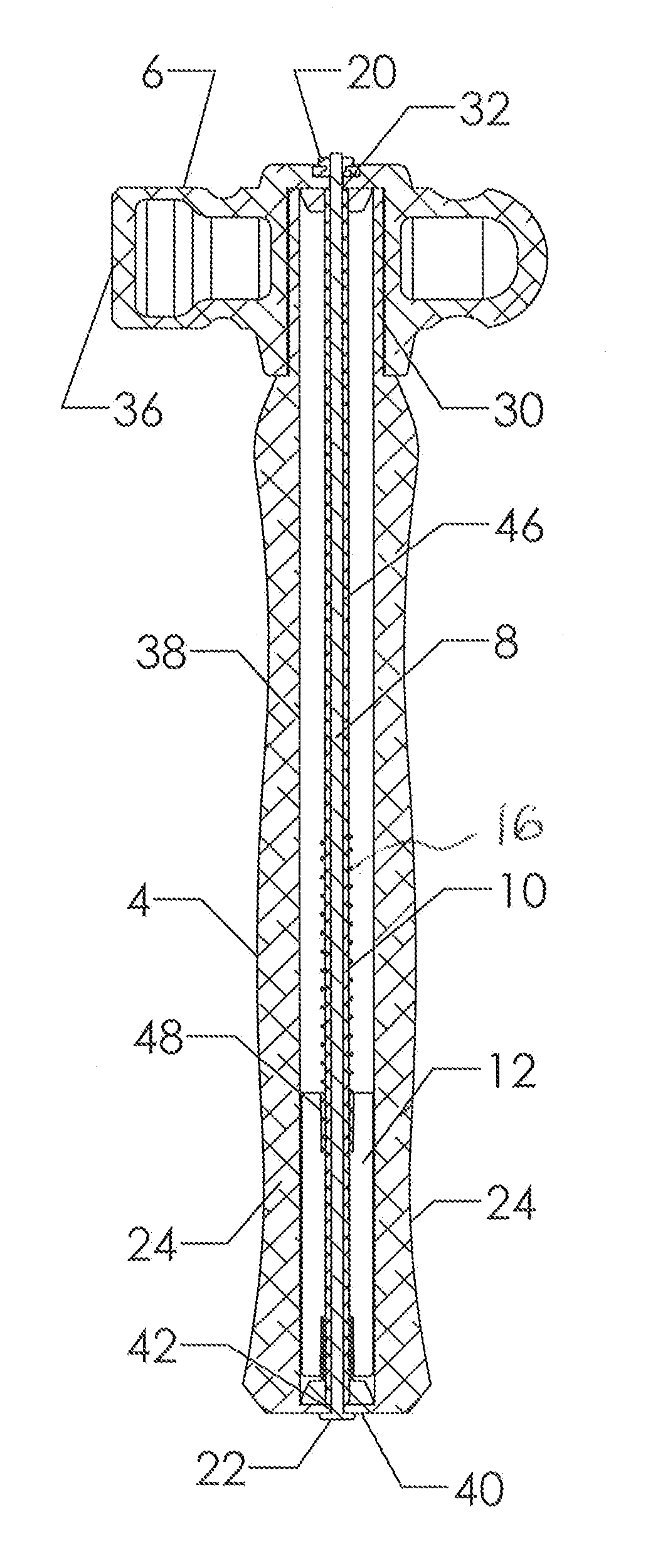
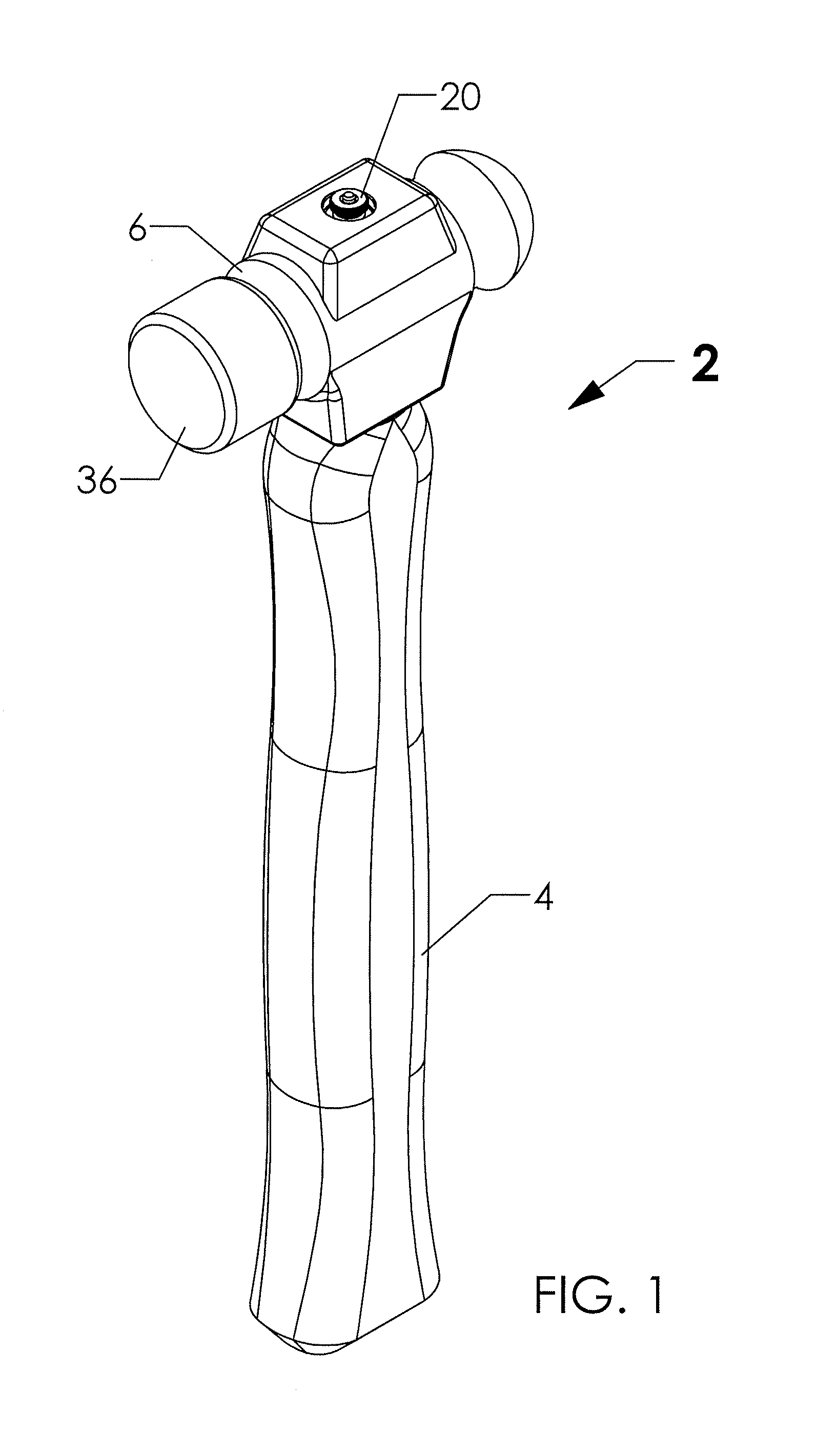
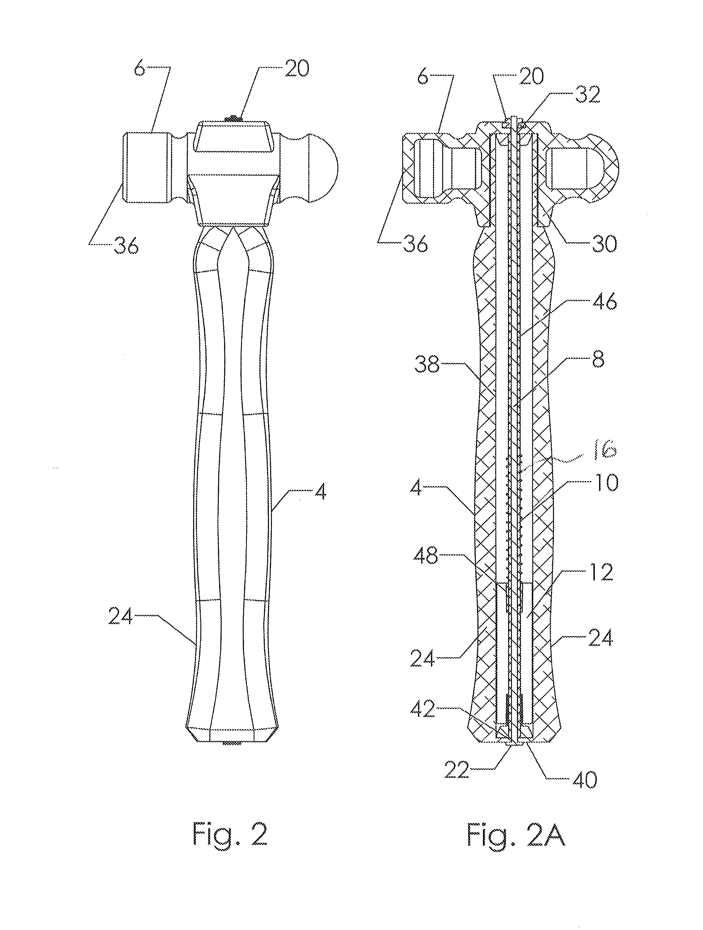
[0033]Turning now to FIGS. 1-3, a brief description concerning the various components of a first embodiment of the present invention will now be briefly discussed. As shown in this embodiment, the striking device 2 generally comprises an elongate handle 4, typically a removable / interchangeable partially lightened or hollow striking head 6, a tensioning shaft 8 having a threaded first end and a head 22 at a second end thereof, a low friction slide tube 10 engages with the tensioning shaft 8 which supports a sliding weight 12, a pair of opposed impact absorption mechanisms, such as springs 16 and / or impact absorption bumpers or e...


PUM

PropertyMeasurementUnit
Weightaaaaaaaaaa
Weightaaaaaaaaaa
Weightaaaaaaaaaa

Abstract

A striking device comprising a striking head, an elongate handle comprising a first end and an opposed second end. The striking head is affixed to the first end while the second end has a hand grip which facilitates gripping of the handle by an operator of the striking device. The handle accommodates a sliding weight which is movable, due to a swinging motion of the striking device, from the first end of the handle toward the second end of the handle to increase an impact force of the striking head as the striking head strikes an object to be struck.

Description

FIELD OF THE INVENTION[0001]The present invention relates generally to striking devices and more specifically relates to striking device incorporating a sliding weight which is movable, by centrifugal force, so as to increase a velocity of the striking device and thereby increase a collision force between a striking head of the striking device and the object to be struck.BACKGROUND OF THE INVENTION[0002]A number of striking devices are known from the prior art. Such know striking devices typically have a head, comprising a fixed weight located at a striking end thereof. That is, the weight of the head of the striking device remains constant as the striking device is utilized to strike a desired object. Depending on the type of striking device, the weight of the head can be anywhere between a few ounces to many pounds. Since a majority of the weight, of such currently known striking devices, is typically fixedly located at the head of such striking devices, it take much effort to swi...

Claims


Application Information

Patent Timeline
IPC IPC(8): B25D1/00B25D1/02
CPCB25D1/02B25D1/00B26B23/00B25D2250/105B25D2250/241B25D2250/391B25G1/102Y10T29/4984
Inventor NEAR, TIMOTHY J.
Owner NEAR TIMOTHY J
Why Eureka
Try Eureka