Torsional rate sensor with momentum balance and mode decoupling

a technology of momentum balance and torsional rate, applied in the direction of instruments, devices using electric/magnetic means, acceleration measurement using interia forces, etc., can solve problems such as unwanted energy transfer to the substrate, and achieve the effect of improving the angular ra

Active Publication Date: 2006-12-07
EMCORE INC
View PDF7 Cites 13 Cited by
  • Summary
  • Abstract
  • Description
  • Claims
  • Application Information

AI Technical Summary

Benefits of technology

[0006] It is in general an object of the invention to provide a new and improved angular rate sensor or gyroscope.

Problems solved by technology

In addition, imperfections in fabrication often result in the masses being of slightly different size, which prevents them from oscillating with equal amplitudes.
The unequal oscillations produce an imbalance in momentum and result in undesired transfer of energy to the substrate.

Method used


Image

  • Torsional rate sensor with momentum balance and mode decoupling
  • Torsional rate sensor with momentum balance and mode decoupling
  • Torsional rate sensor with momentum balance and mode decoupling

Examples


Embodiment Construction

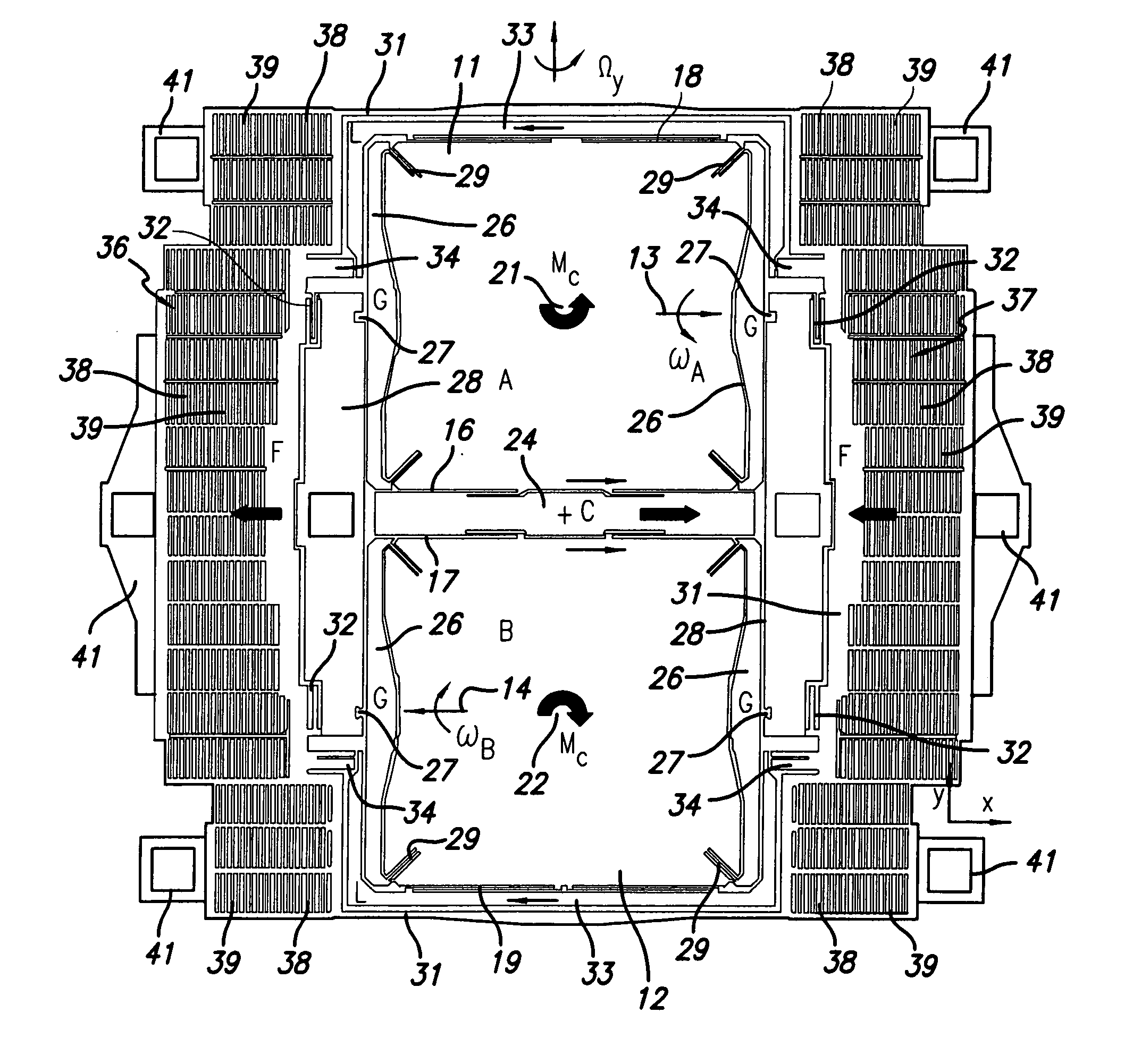
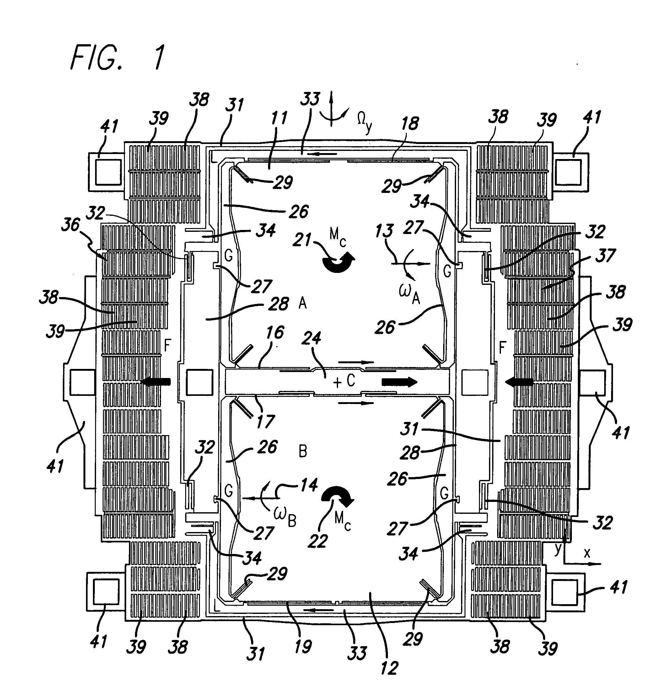
[0016] As illustrated in FIG. 1, the rate sensor has a pair of generally planar proof masses 11, 12 which lie in an x, y reference plane when the device is at rest. The input axis, i.e. the axis about which angular rate of rotation is measured, is the y-axis, and the proof masses are disposed side-by-side along that axis for torsional movement about a pair of drive axes 13, 14 which extend in a direction parallel to the x axis. The proof masses are driven in an anti-phase manner for out-of-phase movement through the reference plane as they pivot about the drive axes, with the inner edges 16, 17 of the two masses moving together in one direction and the outer edges 18, 19 moving together in the opposite direction.

[0017] The proof masses are also mounted for torsional movement about a pair of sense axes 21, 22 which extend in the z-direction, perpendicular to the x, y plane and the other axes. Coriolis forces produced by rotation of the sensor about the y-axis cause the masses to rot...


PUM


Abstract

Rate sensor comprising a plurality of generally planar masses, a drive axis in the plane of each of the masses, means for driving the masses to oscillate about the drive axes, an input axis perpendicular to the drive axes, sense axes perpendicular to the drive axes and the input axis, means mounting the masses for torsional movement about the sense axes in response to Coriolis forces produced by rotation of the masses about the input axis, and means responsive to the torsional movement about the sense axis for monitoring rate of rotation about the input axis.

Description

BACKGROUND OF THE INVENTION [0001] 1. Field of Invention [0002] This invention pertains generally to angular rate sensors or gyroscopes and, more particularly, to a dual mass rate sensor in which momentum is balanced and the drive and sense modes are decoupled. [0003] 2. Related Art [0004] In rate sensors or gyroscopes, the use of two coupled proof masses which oscillate in an out-of-phase manner in the drive mode is a common way of balancing the drive momentum in order to minimize the transfer of energy to the substrate. In addition, with the masses being driven in an anti-phase manner, the response of the masses to Coriolis forces will also be out of phase, which allows the effects of external vibrations to be cancelled. [0005] Out-of-phase oscillation in the drive mode is commonly achieved by coupling the two proof masses together with a spring, which has some significant disadvantages. The resulting dynamic system has two resonances—a parasitic in-phase mode and the desired out-...

Claims


Application Information

Patent Timeline
Patent Type & Authority Applications(United States)
IPC IPC(8): G01P15/14
CPCG01C19/5719G01C19/5712
Inventor ACAR, CENKMAO, MINYAOCOSTLOW, LYNN EDWARD
Owner EMCORE INC
Why Eureka
Try Eureka