Force balanced impeller flow meter for mass flow rate control

a flow meter and impeller technology, applied in the field of mass flow meter, can solve the problem that the device is therefore inadequate for applications, and achieve the effect of enhancing the flow induced torque and increasing the angular velocity of the fluid

Inactive Publication Date: 2009-10-20
ROSEMOUNT AEROSPACE
View PDF7 Cites 14 Cited by
  • Summary
  • Abstract
  • Description
  • Claims
  • Application Information

AI Technical Summary

Benefits of technology

[0010]The mass flow meter further includes an elongated flow swirler that communicates with an inlet end of the fluid flow path through the impeller body. The flow swirler is configured to impart a helical flow pattern about the axis of flow to fluid passing therethrough, which increases the angular velocity of the fluid about the axis of flow. This enhances the flow induced torque exerted on the impeller body, and is advantageous given the relatively low flow rate of the fluid delivered to the impeller body. Preferably, the flow swirler comprises a thin-walled pipe having an elliptical cross-section, helically twisted about its longitudinal axis. Alternatively, the flow swirler may comprise a tube having a helical insert therein for imparting a helical flow to fluid passing therethrough or a pair of entwined tubes.

Problems solved by technology

The device is therefore inadequate for applications that involve small fuel flow rates, such as the flow rates expected in distributed control applications.

Method used


Image

  • Force balanced impeller flow meter for mass flow rate control
  • Force balanced impeller flow meter for mass flow rate control
  • Force balanced impeller flow meter for mass flow rate control

Examples


Embodiment Construction

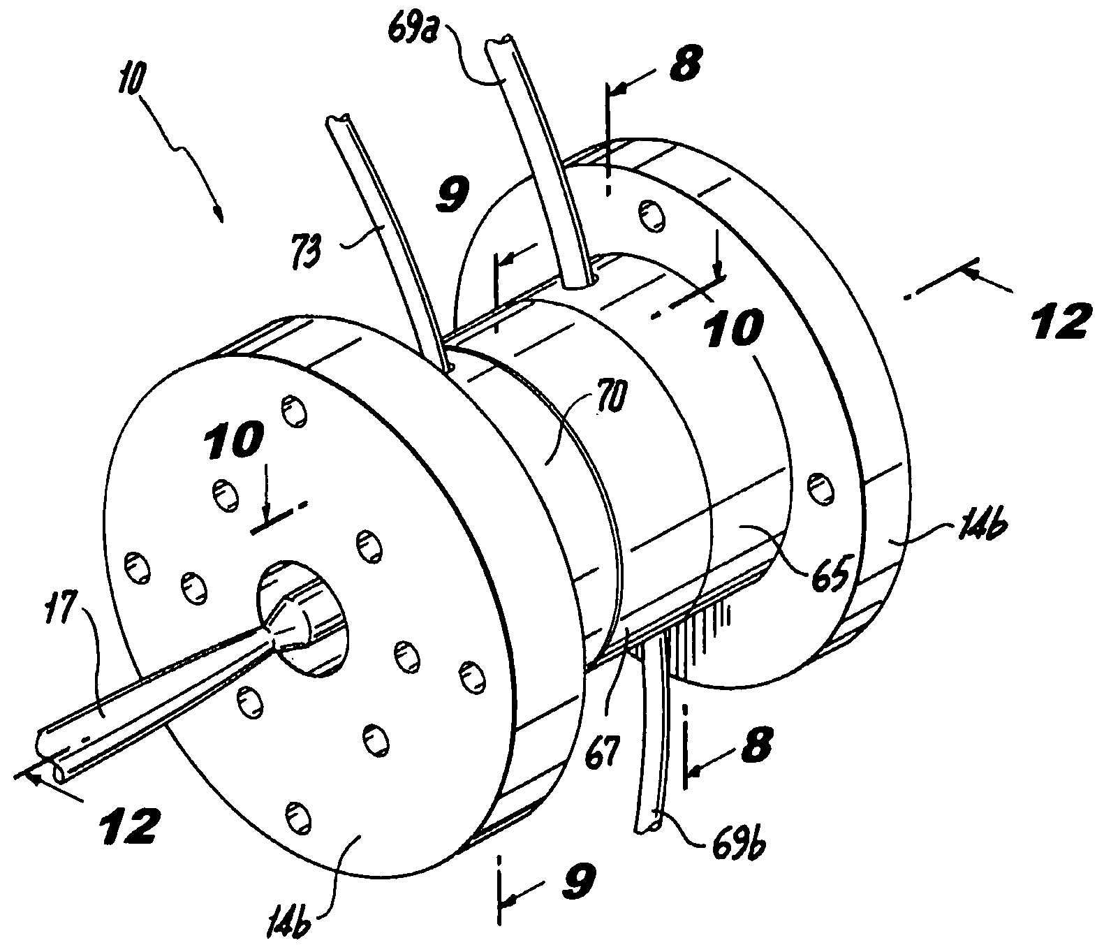
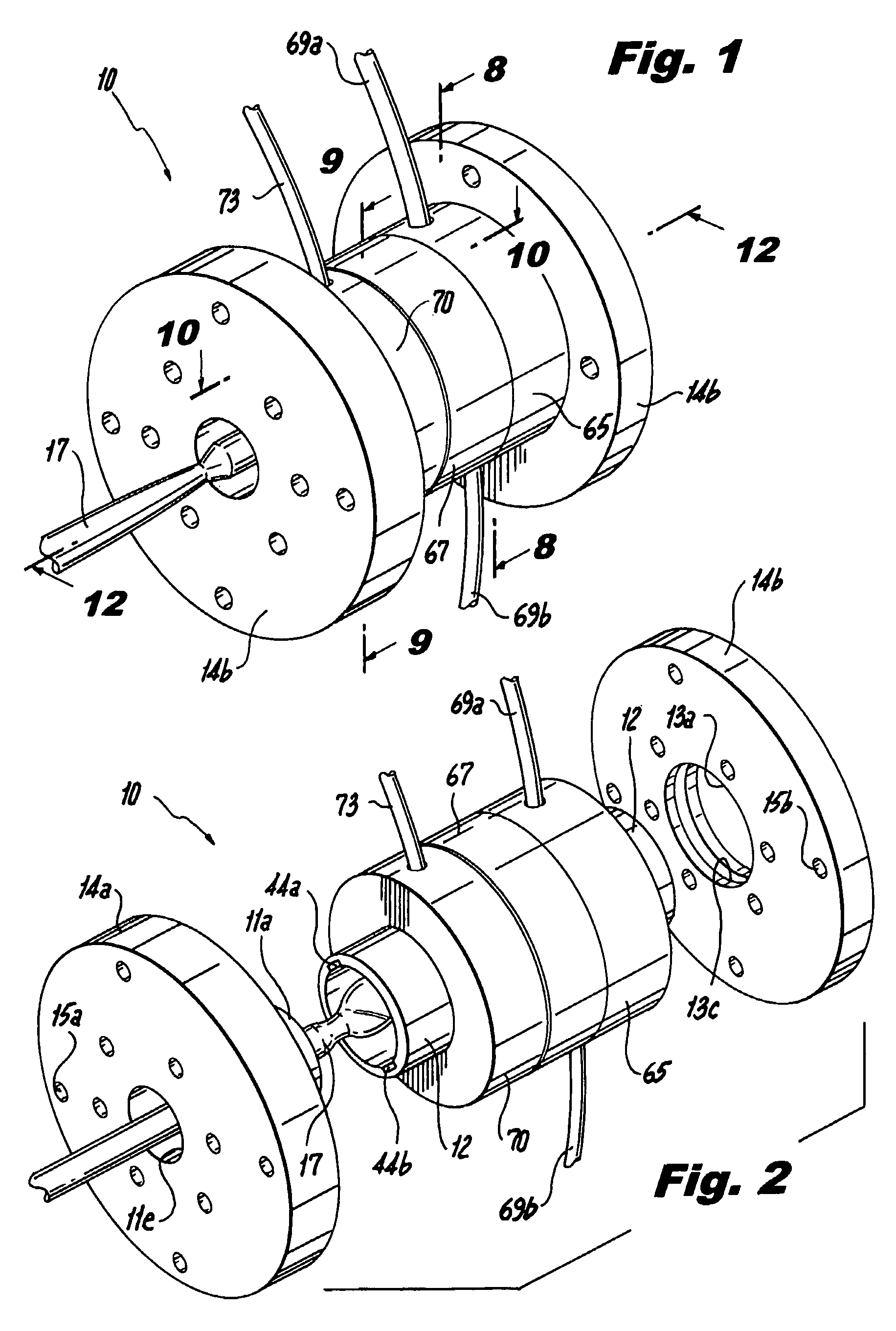
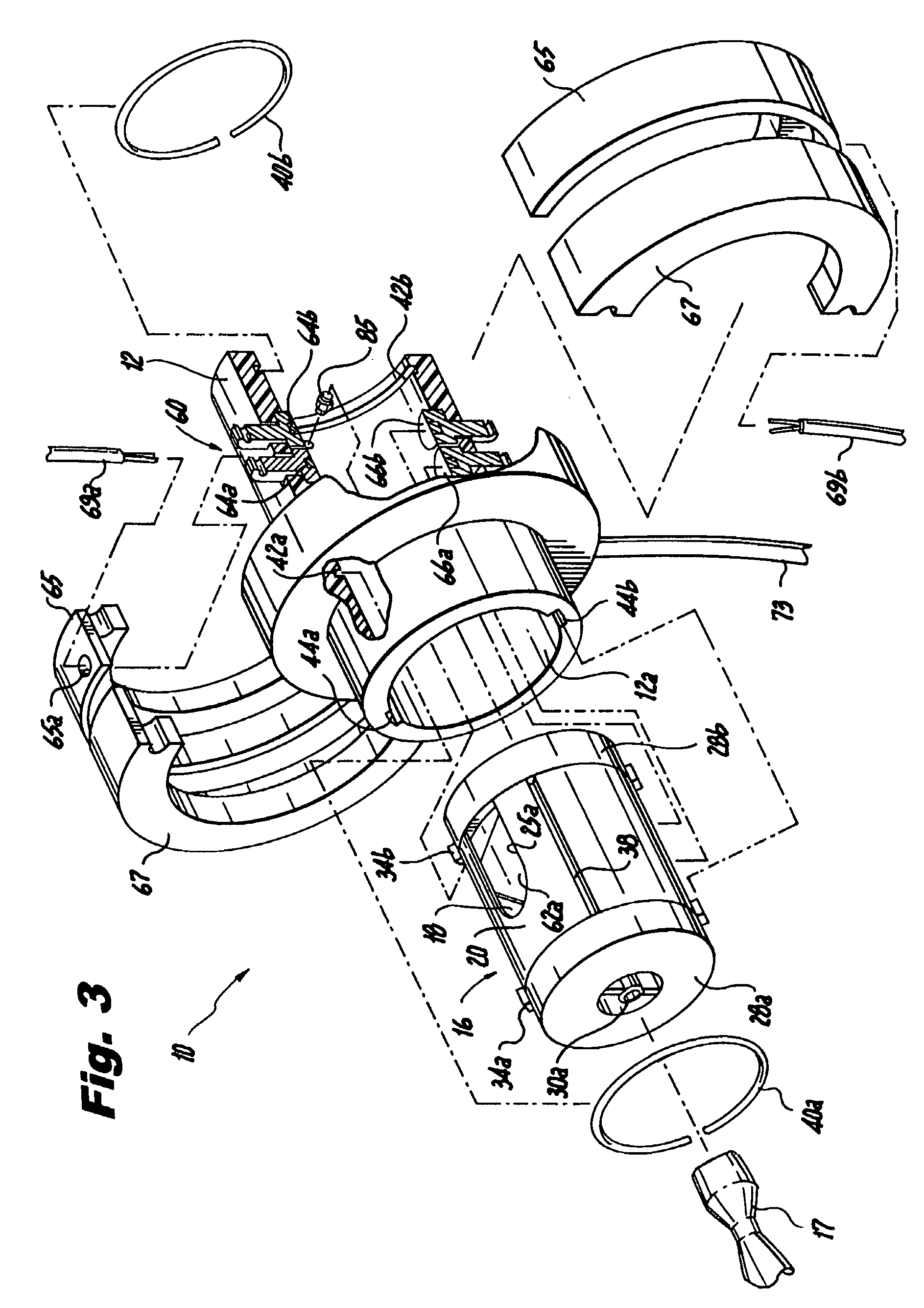
[0036]Referring now to the drawings wherein like reference numerals identify or otherwise refer to similar structural features or elements of the various embodiments of the subject invention, there is illustrated in FIG. 1 a force balanced mass flow meter constructed in accordance with a preferred embodiment of the subject invention and designated generally by reference numeral 10. The mass flow meter 10 of the subject invention is essentially an electro-mechanical transducer for computing mass flow rate or fluid density (e.g., mass fuel flow rate or fuel density). The device is designed to respond accurately with respect to relatively small flow rates and is particularly well adapted for use in conjunction with the distributed control architecture of an active combustion control system for a gas turbine engine. An active combustion control system in disclosed for example in U.S. patent application Ser. No. 11 / 601,301, the disclosure of which is herein incorporated by reference in i...


PUM


Abstract

A force balanced mass flow meter is disclosed that includes a cylindrical sensor housing having an interior bore, an impeller body supported for axial rotation within the interior bore of the sensor housing, and including structure for converting fluid inertia into flow induced torque when fluid flows relative to the impeller body, a proximity sensor for measuring a rotation angle of the impeller body relative to the sensor housing, an electromagnet for generating a magnetic field about the sensor housing to prevent rotation of the impeller body, electronics for determining electrical values from the proximity sensor when fluid flows relative to the impeller body and a controller for controlling current supplied to the electromagnet in response to electrical values determined from the proximity sensor, to generate a magnetic field sufficient to prevent impeller rotation.

Description

BACKGROUND OF THE INVENTION[0001]1. Field of the Invention[0002]The subject invention is directed to a mass flow meter for characterizing the mass flow rate of a fluid, and more particularly, to a force balanced impeller flow meter for mass flow rate control of a fuel in a gas turbine engine.[0003]2. Description of Related Art[0004]The next generation of gas turbine engines will likely include distributed flow architecture, wherein fuel flow to individual injector nozzles will be selectively modulated by an active fuel delivery control system. Distributed control architecture requires individual mass flow rate control at each nozzle. This will require smaller mass flow sensors with faster response times that can operate at relatively small flow rates. The estimated flow rates are expected to be about an order of magnitude less than those of conventional main flow stream meters.[0005]A well known prior art main flow stream meter for accurately measuring fuel flow rates in gas turbine...

Claims


Application Information

Patent Timeline
Patent Type & Authority Patents(United States)
IPC IPC(8): G01F1/80
CPCG01F1/78G01F1/28
Inventor SPIVAK, ALEXANDERERIKSEN, ODD HARALD STEENGOLDENBERG, FELIXGRICHENER, ALEXANDERSANDEN, CHRISTOPHERMCTIGHE, JOELIN, CHUANG-CHIA
Owner ROSEMOUNT AEROSPACE
Why Eureka
Try Eureka