Laboratory centrifuge with swing-out containers and aerodynamic cladding

a technology of swing-out containers and centrifuges, which is applied in the direction of centrifuges, instruments, specific gravity measurement, etc., can solve the problems of unrestricted applicability of centrifuges, achieve optimal aerodynamic improvement, reduce centrifugal forces, and reduce air turbulence

Inactive Publication Date: 2006-12-19
EPPENDORF AG
View PDF17 Cites 14 Cited by
  • Summary
  • Abstract
  • Description
  • Claims
  • Application Information

AI Technical Summary

Benefits of technology

[0014]The objective of the present invention is to create a rotor of the above species that shall generate little heat and little noise while being devoid of an air chamber, yet at high angular speeds and low motor power.
[0015]The present invention calls for an aerodynamic cladding component at each rotor arm and / or at each container, said cladding components aerodynamically improving the containers at least at their radially outermost zones. Energy effects from the incident airflow such as generated heat and noise increase as the 4th power of the radial distance from the rotor axis. In the swung-out state, that is at high angular speeds, the containers project beyond the rotor arms and they constitute the radially outermost zones where the highest air speeds are encountered. Aerodynamic cladding is at its most critical in said outermost zones because of the interference increasing as the fourth power of the radius. In said zones, aerodynamic cladding shall very markedly reduce air turbulence. Air drag is considerably reduced and therefore substantially less motor power suffices. Again the air-turbulence generated heat is also much reduced, as is the noise. An air chamber no longer is required, hence the samples in the containers can be thermostatted as desired by heating and cooling elements in the centrifuge housing. The containers therefore may retain their shapes, which otherwise would be aerodynamically undesirable, whereby their applicability is now unrestricted. The cladding components may be in the form of simple and economical add-on elements which illustratively may also be used to retrofit known rotors of the above species.

Problems solved by technology

The containers therefore may retain their shapes, which otherwise would be aerodynamically undesirable, whereby their applicability is now unrestricted.

Method used


Image

  • Laboratory centrifuge with swing-out containers and aerodynamic cladding
  • Laboratory centrifuge with swing-out containers and aerodynamic cladding
  • Laboratory centrifuge with swing-out containers and aerodynamic cladding

Examples


Embodiment Construction

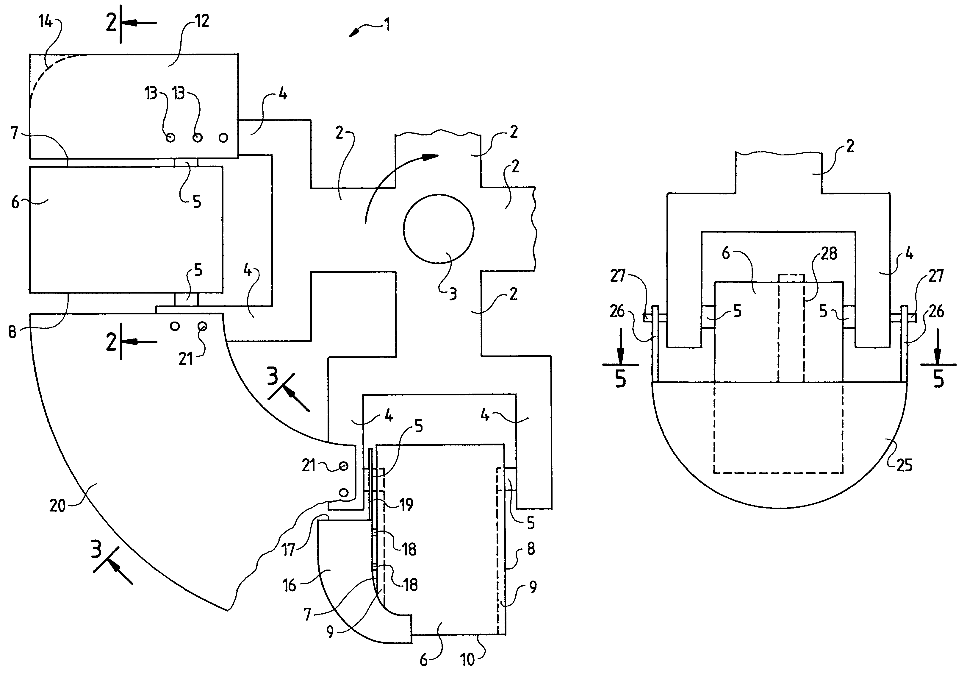
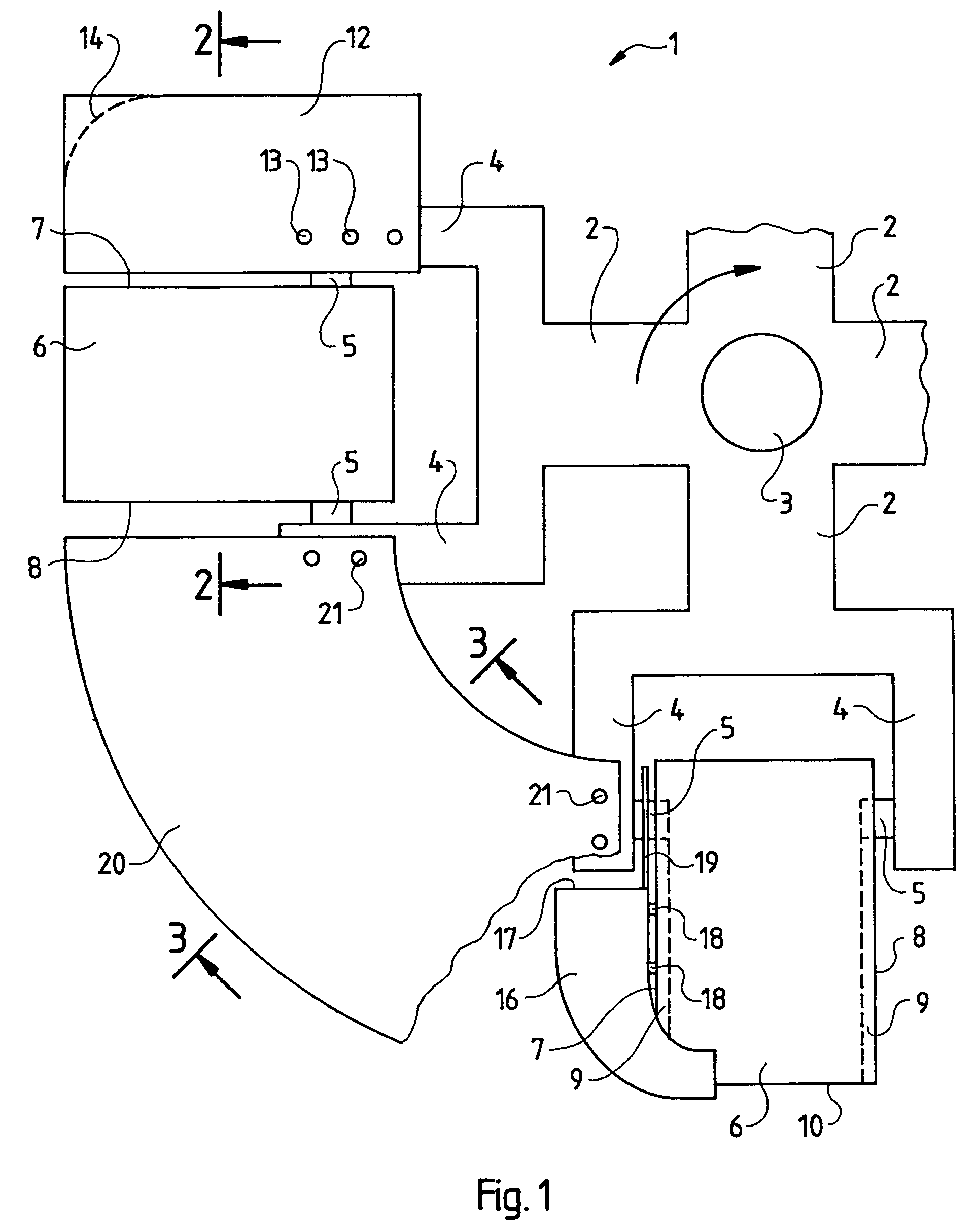
[0031]FIG. 1 is a top view of a laboratory centrifuge rotor 1. In this embodiment mode, said rotor comprises four rotor arms 2 and rests on a vertical shaft 3 driven by an omitted motor in the direction of rotation indicated by the arrow. The overall assembly is enclosed by a safety housing which comprises an upper cover element allowing access from above to the rotor as shown in FIG. 1. More information may be found about this design in the initially cited brochure pages.

[0032]The rotor arms 2 change radially outward into fork arms 4 fitted with inwardly projecting pivot pins 5 from which containers 6 can be suspended between the fork arms 4.

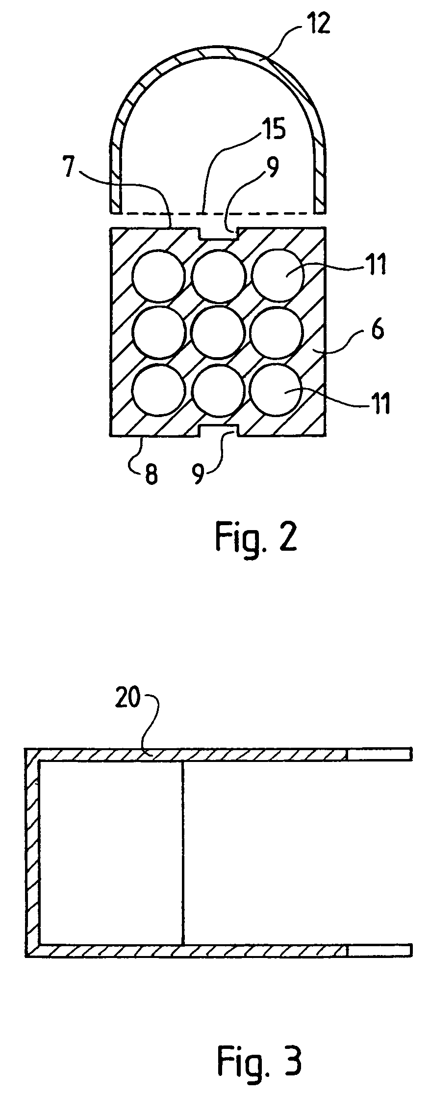
[0033]As shown by FIG. 2, the containers 6 of this embodiment mode exhibit a substantially square cross-section and each is fitted as seen in the direction of motion at its front end face and at its rear end face 8 with a longitudinal groove 9 that is open relative to the plane bottom surface 10 of the container 6 and closed in rounded manner a...


PUM


Abstract

The invention relates to a laboratory centrifuge rotor (1) running in air and devoid of an air chamber, comprising rotor arms (2) ending in fork arms (4), containers (6) swinging out on pivot pins (5) being suspended between said arms (2), said rotor being characterized in that an aerodynamic cladding component (12, 16, 20, 25) is mounted ahead as seen in the direction of motion on each rotor arm (2, 4) and / or ahead of each container (6) in at least the radially outermost regions of the zones (7) facing the incident airflow of the swung-out containers (6).

Description

BACKGROUND OF THE INVENTION[0001]1. Field of the Invention[0002]The present invention relates to the field of laboratory centrifuge rotors.[0003]2. Description of Related Art[0004]A standard laboratory centrifuge rotor design offers the advantage of swing-out containers where the direction of force remains constant at all angular speeds. The containers being movable outward, they can be removed from the rotor and be conveniently loaded / unloaded outside the centrifuge. The containers may assume different shapes in order to accept different kinds of sample containers. This feature ranges from large bottles to sample tubules to stacks of microtiter plates received in an open, boxy container.[0005]To generate very high forces shortening centrifuging time, centrifuges of the above species run at very high angular speeds. In the process, the rotor together with the containers is then exposed to very high incident airflows.[0006]In the standard design, the containers preponderantly are des...

Claims


Application Information

Patent Timeline
Patent Type & Authority Patents(United States)
IPC IPC(8): B04B5/02B04B5/04
CPCB04B5/0421
Inventor LURZ, WERNER
Owner EPPENDORF AG
Why Eureka
Try Eureka