
Wire heated tube with temperature control system for humidifier for respiratory apparatus

a technology of temperature control system and humidifier, which is applied in the direction of respirators, heat measurement, instruments, etc., can solve the problem that prior art devices do not provide accurate temperature measurements during continuous use of heated tubes or conduits, and achieve the effect of preventing overheating of heating plates

Active Publication Date: 2014-08-07
RESMED LTD
View PDF3 Cites 71 Cited by
  • Summary
  • Abstract
  • Description
  • Claims
  • Application Information

AI Technical Summary

Benefits of technology

The patent aims to provide a respiratory apparatus with a heated tube or conduit to deliver warm and / or humidified air to a patient while minimizing condensation. The heating plate of the humidifier and the heated tube can be controlled to prevent overheating. The technical effects of this invention include efficient delivery of breathable gas to patients through heated and humidified air, as well as prevention of overheating and condensation in the delivery system.

Problems solved by technology

None of these prior art devices provide accurate temperature measurements during continuous use of a heated tube or conduit.

Method used


Image

  • Wire heated tube with temperature control system for humidifier for respiratory apparatus
  • Wire heated tube with temperature control system for humidifier for respiratory apparatus
  • Wire heated tube with temperature control system for humidifier for respiratory apparatus

Examples


Embodiment Construction

PAP System

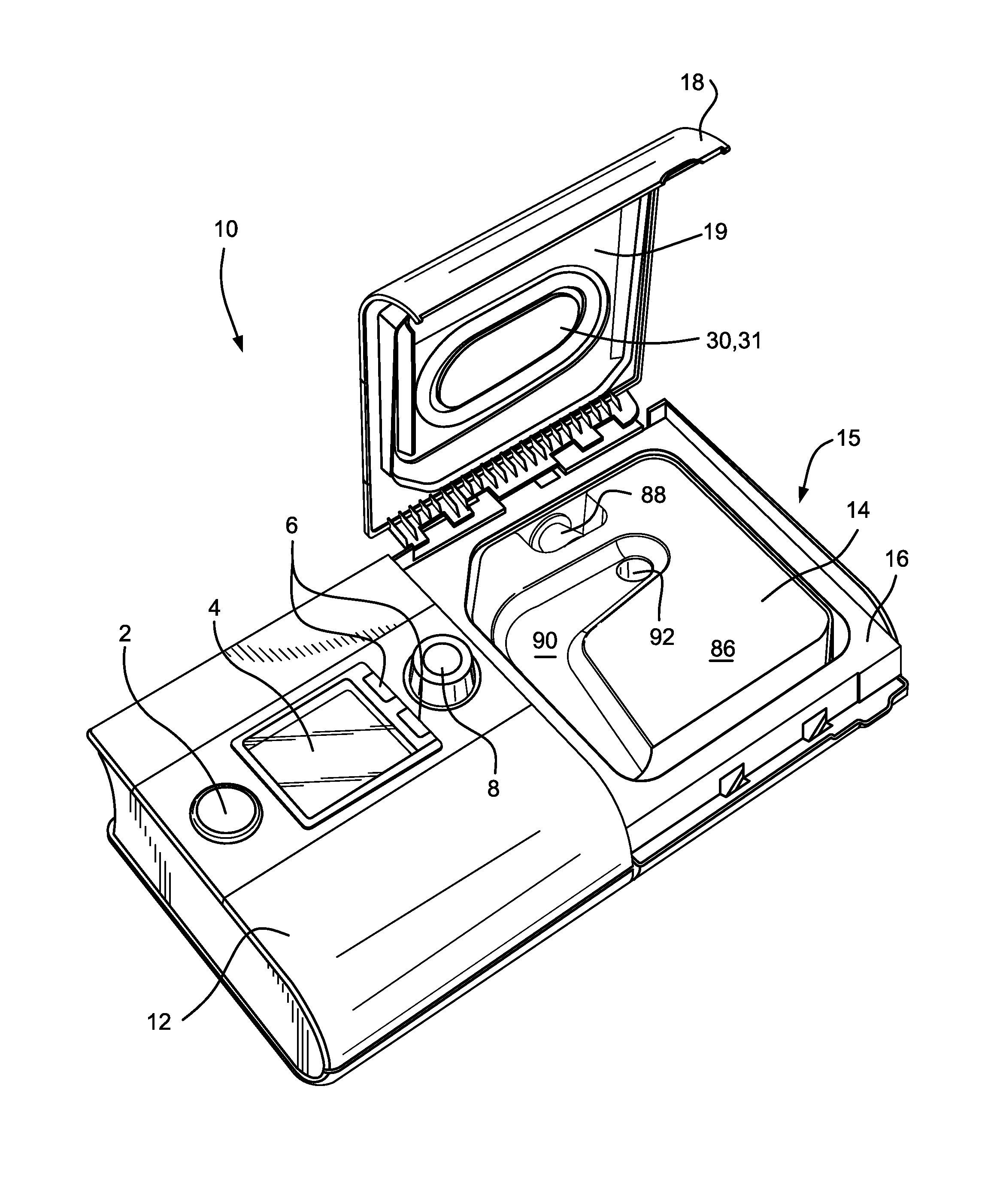
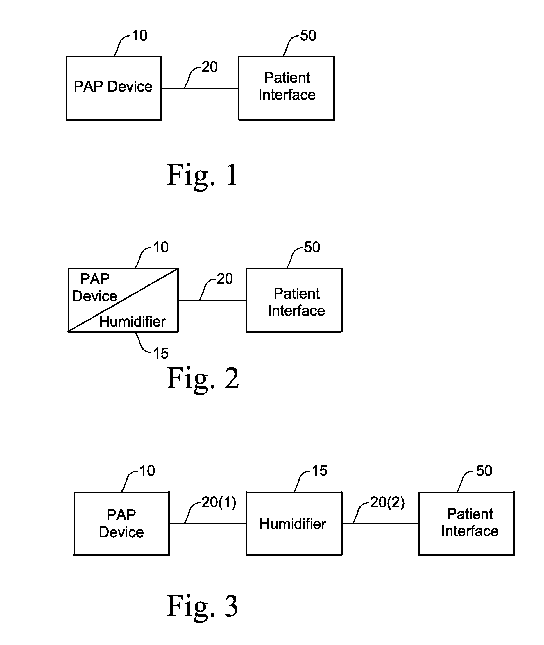
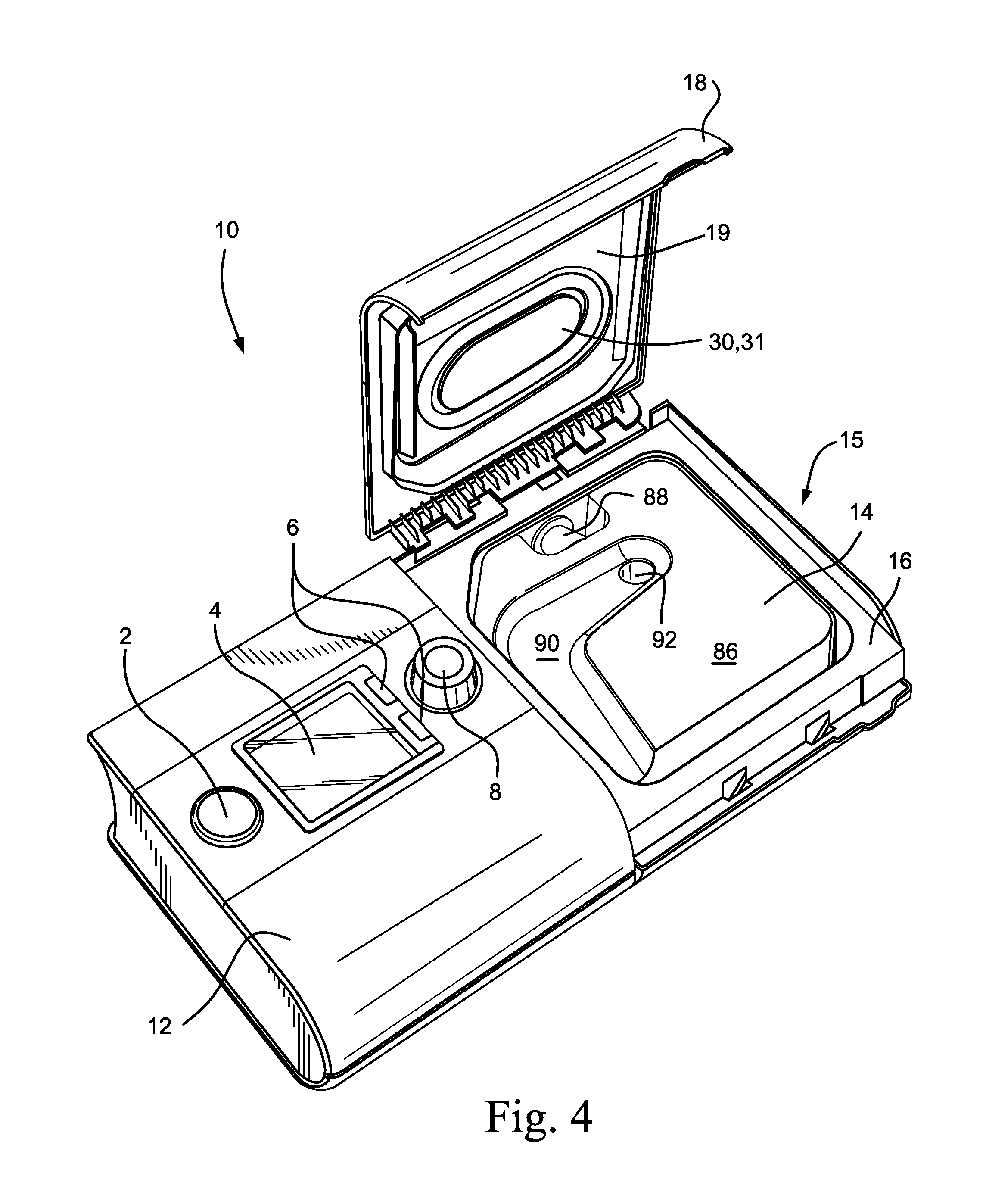
[0062]As schematically shown in FIG. 1, a Positive Airway Pressure (PAP) system, for example a Continuous Positive Airway Pressure (CPAP) system, generally includes a PAP device (or PAP system or respiratory apparatus) 10, an air delivery conduit 20 (also referred to as a tube or tubing), and a patient interface 50. In use, the PAP device 10 generates a supply of pressurized air that is delivered to the patient via an air delivery conduit 20 that includes one end coupled to the outlet of the PAP device 10 and an opposite end coupled to the inlet of the patient interface 50. The patient interface comfortably engages the patient's face and provides a seal. The patient interface or mask may have any suitable configuration as is known in the art, e.g., full-face mask, nasal mask, oro-nasal mask, mouth mask, nasal prongs, etc. Also, headgear may be utilized to comfortably support the patient interface in a desired position on the patient's face.

[0063]In embodiments, a humidifie...


PUM


Abstract

A PAP system for delivering breathable gas to a patient includes a flow generator to generate a supply of breathable gas to be delivered to the patient; a humidifier including a heating plate to vaporize water and deliver water vapor to humidify the supply of breathable gas; a heated tube configured to heat and deliver the humidified supply of breathable gas to the patient; a power supply configured to supply power to the heating plate and the heated tube; and a controller configured to control the power supply to prevent overheating of the heating plate and the heated tube.

Description

CROSS-REFERENCE TO RELATED APPLICATIONS[0001]This application claims the benefit of Australian Provisional Application No. 2013900328, filed Feb. 1, 2013, the entire contents of which are incorporated herein by reference.BACKGROUND OF THE INVENTION[0002]1. Field of the Invention[0003]The present technology relates to humidification and heater arrangements used to control the humidity of breathable gases used in all forms of respiratory apparatus ventilation systems including invasive and non-invasive ventilation, Continuous Positive Airway Pressure (CPAP), Bi-Level therapy and treatment for sleep disordered breathing (SDB) conditions such as Obstructive Sleep Apnea (OSA), and for various other respiratory disorders and diseases.[0004]2. Description of Related Art[0005]Respiratory apparatus commonly have the ability to alter the humidity of the breathable gas in order to reduce drying of the patient's airway and consequent patient discomfort and associated complications. The use of a...

Claims


Application Information

Patent Timeline
IPC IPC(8): A61M16/10A61M16/08A61M16/00
CPCA61M16/1095A61M16/0883A61M16/0057A61M16/0003G01K7/24G01K13/02G01K13/024A61M16/16A61M2205/3368
Inventor VOS, ADRIAN ASHLEYHUBY, RONALD JAMESTANG, ZHUO RAN
Owner RESMED LTD
Learn More