Droplet discharge device and method

a technology of droplet and discharge device, which is applied in the direction of inking apparatus, manufacturing tools, and solventing apparatus, etc., can solve the problems of affecting the discharge accuracy of droplets, and requiring contrivance, so as to reduce the discharge accuracy

Active Publication Date: 2014-08-07
MUSASHI ENG INC
View PDF4 Cites 14 Cited by
  • Summary
  • Abstract
  • Description
  • Claims
  • Application Information

AI Technical Summary

Benefits of technology

[0027]According to the present invention, the droplet can be high-accurately discharged in a minute volume at which it has so far been impossible to discharge the droplet without contacting the plunger (valve body) with the inner wall of the liquid chamber (valve seat).
[0028]Furthermore, since the valve body and the valve seat are not contacted with each other, friction debris or particles are not generated and hence not mixed into the liquid material. Accordingly, contamination-free discharge of the liquid material in a minute amount can be realized.
[0029]In addition, even when the liquid material contains a solid substance, e.g., filler, reduction of discharge accuracy caused by collapse or breakage of the solid substance is avoided, and the discharge can be performed without impairing the function and the properties of the liquid material.

Problems solved by technology

However, hitting the plunger against the valve seat raises the problems that the shape of the plunger is changed due to wear, and that wear dust or wear debris generates and contaminates the liquid material, or comes into a gap between the plunger and the valve seat, whereby satisfactory discharge is impeded.
However, there is a problem of requiring a contrivance, such as half-etching, in a situation where the 0402 component is present together with large-sized components.
Another problem is that a coating amount (coating thickness) has to be controlled individually.
For that reason, the mounting with the printing is poor in yield.
Moreover, component layout is limited in some cases when good printing performance is to be ensured.
In that type of device, however, there is not yet realized a technique of high-accurately discharging a droplet of a liquid, such as a solder paste, in a minute volume (e.g., several tens to several hundreds μm in terms of a diameter of the landed droplet), which is required for a small-sized component, without contacting the plunger with the valve seat.

Method used


Image

  • Droplet discharge device and method
  • Droplet discharge device and method
  • Droplet discharge device and method

Examples


example 1

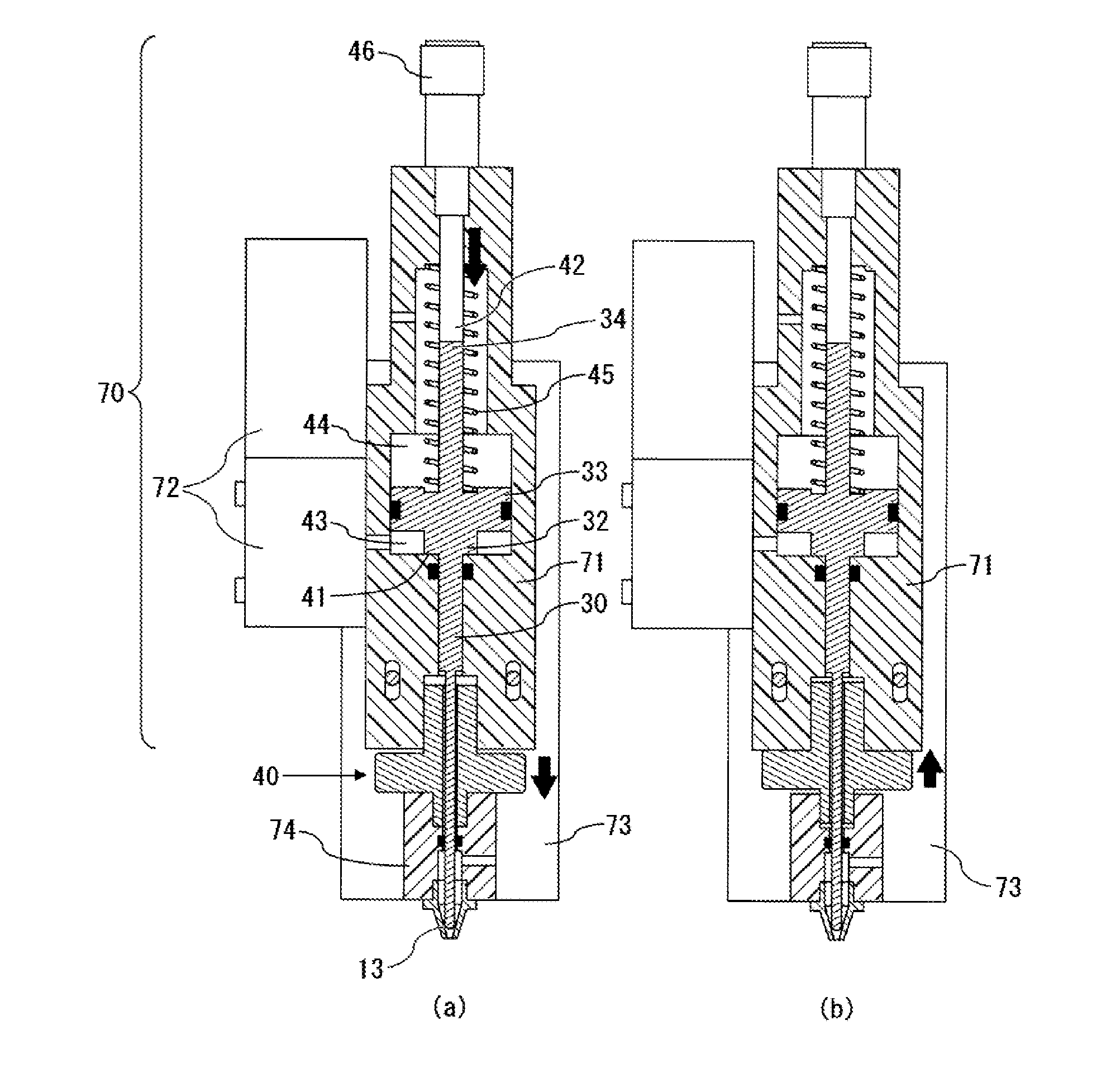
[0076]A droplet was formed by the droplet discharge device illustrated in FIG. 1. The liquid material used in Example 1 was a solder paste (viscosity: 45000 mPa·s) containing filler with a mean particle size of 6 μm. A volume of one droplet discharged in this Example was 0.2 nl, and a diameter of the landed droplet was 120 μm. From a test of forming several tens of droplets on a workpiece at a tact of 100 shots per second while moving the workpiece and the discharge opening relative to each other, it was confirmed as a result of measurement using a measuring device that dots having uniform shapes were formed.

example 2

[0077]A droplet was formed by the droplet discharge device illustrated in FIG. 1. The liquid material used in Example 2 was an Ag paste (viscosity: 28000 mPa·s) containing flake-shaped filler in the range of 1 to 10 μm. A volume of one droplet discharged in this Example was 0.17 nl, and a diameter of the landed droplet was 100 μm. From a test of forming several tens of droplets on a workpiece at a tact of 250 shots per second while moving the workpiece and the discharge opening relative to each other, it was confirmed as a result of measurement using a measuring device that dots having uniform shapes were formed.


PUM


Abstract

An example of droplet discharge device includes a discharge path (12) having an end that constitutes a discharge opening (11), a plunger (30), a liquid chamber (50) into which the plunger (30) is inserted, a plunger driving mechanism that moves the plunger (30) forward and backward, and a plunger position determining mechanism that specifies a position of a tip portion of the plunger (30). The liquid material is discharged in a droplet state by applying inertial force to the liquid material with forward movement of the plunger (30) in a state where the tip portion of the plunger (30) and an inner wall of the liquid chamber (50) are not contacted with each other. A minute droplet is formed by moving the plunger (30) forward to push the liquid material out of the discharge opening (11) in an amount necessary to form a droplet of a desired size.

Description

TECHNICAL FIELD[0001]The present invention relates to a droplet discharge device and method for high-accurately discharging a minute amount of liquid material ranging from a low-viscosity material, such as water, a solvent or a reagent, to a high-viscosity material, such as a solder paste, a silver paste or an adhesive, regardless of whether the liquid material contains filler or not.BACKGROUND ART[0002]Various techniques have hitherto been proposed in relation to a droplet discharge device for discharging a small amount of liquid material from a discharge opening by using a plunger that is moved reciprocally.[0003]As an example of a droplet discharge device of the type hitting a tip of a plunger against a valve seat to discharge a liquid material in a droplet state, Patent Document 1 discloses a droplet discharge device for causing the liquid material to land on a workpiece after a droplet has departed from a nozzle, wherein a plunger is disposed in a flow path including a valve se...

Claims


Application Information

Patent Timeline
Patent Type & Authority Applications(United States)
IPC IPC(8): B65D47/18
CPCB65D83/0022B05C5/0225B41J2/04B41J2/14H05K3/0091H05K3/1241B41J2202/05H05K2203/0126B23K3/0638
Inventor IKUSHIMA, KAZUMASA
Owner MUSASHI ENG INC
Why Eureka
Try Eureka