Electricity Generation Device and Method

Active Publication Date: 2014-08-07
HIGHVIEW ENTERPRISES LTD
View PDF11 Cites 20 Cited by
  • Summary
  • Abstract
  • Description
  • Claims
  • Application Information

AI Technical Summary

Benefits of technology

[0017]The cryogenset is powered by the expansion of a high pressure gas through an expansion turbine, which in turn drives a generator to produce electricity. The high pressure gas is generated by a first compression of a cryogenic fluid, typically air or nitrogen, in a pump, followed by evaporation of the cryogenic fluid within an evaporator. In systems not according to the present invention, evaporation of the cryogenic fluid uses ambient heat alone and requires a large number of ambient vaporisers. Such vaporisers are typically constructed from a finned tube through which the cryogenic fluid passes. Heat is transferred through the fins to the ambient environment. In such systems, the fins and tubes must not be positioned too close together or excessive ice will build up on the fins resulting in a degradation of performance and potentially mechanical damage to the equipment due to the weight of the ice. This problem is particularly relevant to, and is addressed by, the cryogenset of the present invention, as a large quantity of cryogenic fluid must be heated in a short space

Problems solved by technology

Such generating assets, often referred to as peaking plant, burn fossil fuels at low efficiency and can be a significant source of atmospheric pollutants.
In addition, the loss of power from the electricity distribution network can result in significant economic loss to some consumers, such as a data centre, or danger to personnel, for example in the event of a power failure at a hospital.
It would be uneconomic to install a

Method used


Image

  • Electricity Generation Device and Method
  • Electricity Generation Device and Method
  • Electricity Generation Device and Method

Examples


Example

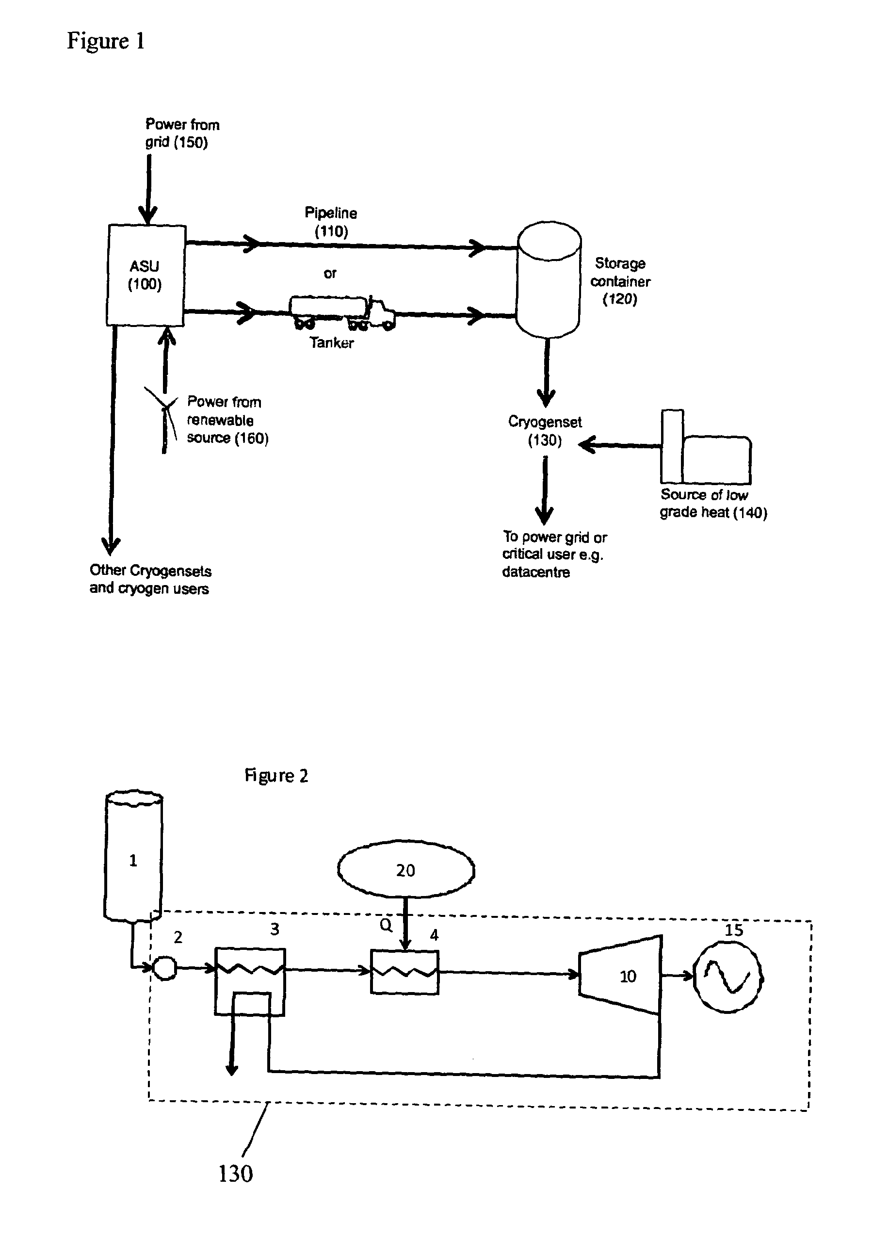
[0027]In a first embodiment of the present invention shown in FIG. 2, cryogenic liquid is received from at least one storage tank 1 and compressed to high pressure, typically greater than 70 bar but less than 200 bar, by at least one liquid pump 2. The high pressure liquid is then evaporated using an evaporator 3 which is connected, on the heating side, to the exhaust of an expansion turbine 10. The now gaseous high pressure fluid is then further heated by another heat exchanger (referred to as the superheater) 4 using heat, Q, from a source, or sources, of low grade heat 20, such as a thermal power station or industrial process. The gas is then expanded through the expansion turbine 10 to generate motive power which in turn drives a generator 15 to produce electricity. The low pressure exhaust gas from the turbine, which is at or slightly above atmospheric pressure (typically 1 to 2 bar), is then returned to the evaporator 3 to evaporate more of the incoming high pressure cryogenic...

Example

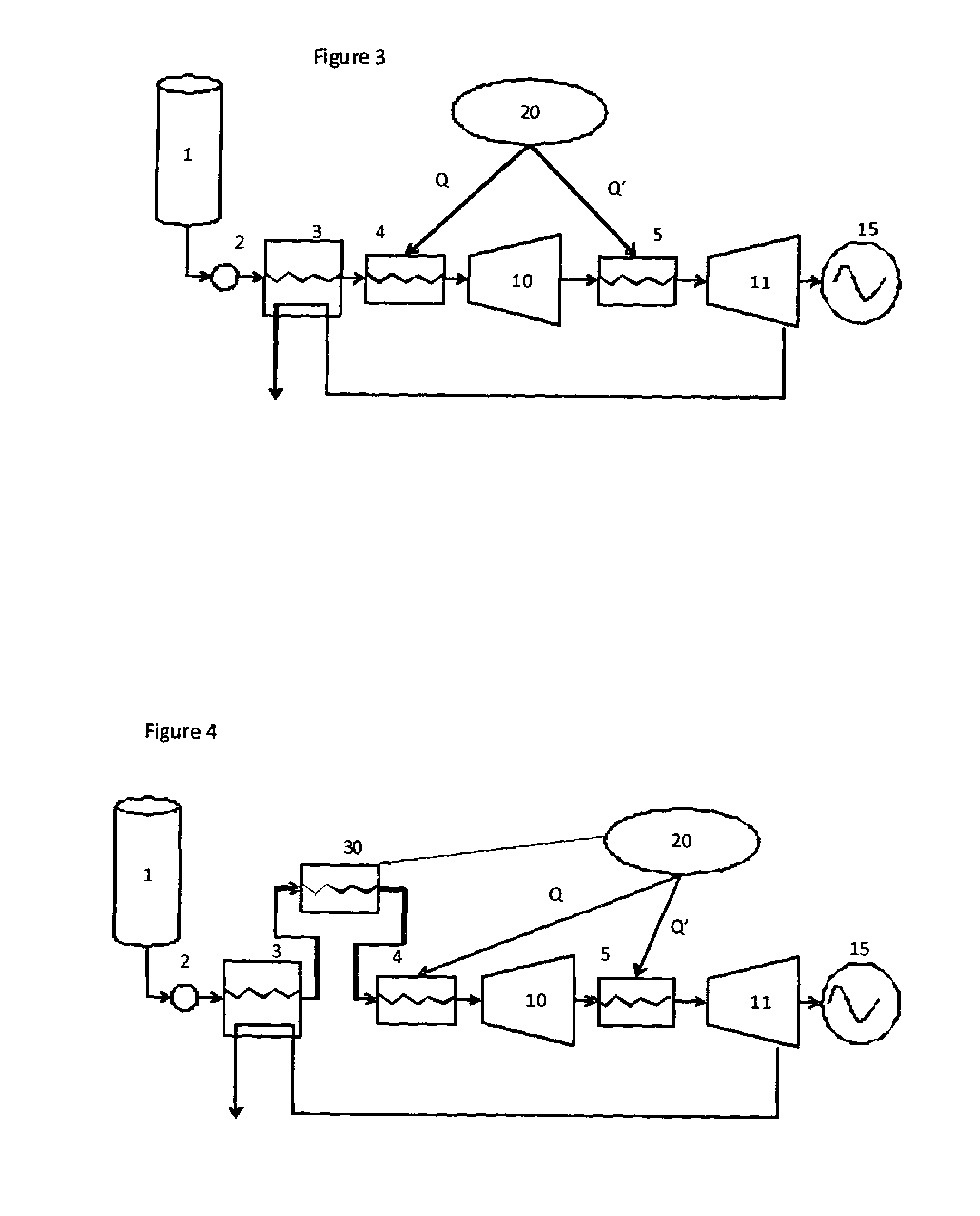
[0028]In a second embodiment of the invention as shown in FIG. 3, the high pressure gas is expanded in two turbine stages 10, 11 to improve the efficiency of the process. Although two stages 10, 11 are shown in FIG. 3, more than two turbine stages can be used. The efficiency is further improved by reheating the part expanded gas between each turbine stage using another heat exchanger, (referred to as a reheater) 5 and low grade waste heat, Q′, from at least one source of waste heat 20. In all other respects the system of FIG. 3 is the same as that of FIG. 2. The source of waste heat 20 used in the reheater 5 may be the same source or a different source to that used in the superheater 4. The low pressure exhaust gas from the final turbine stage 11 is then returned to the evaporator 3 to evaporate the incoming high pressure cryogenic liquid.

[0029]When the source of low grade waste heat 20 is at a temperature above 150° C., there are few cost effective heat transfer fluids that can ope...


PUM


Abstract

There is disclosed a device and method for the generation of zero emission electricity that can be used to provide load balancing and emergency support to a electricity distribution network or back up electricity to a critical consumer such as a hospital or data centre. The system uses a cryogenic fluid and a source of low grade waste heat. A cryogenic fluid is first evaporated by an evaporator (3) heated by a superheater (4) before entering an expansion turbine (10) to produce electricity

Description

FIELD OF THE INVENTION[0001]The present invention relates to electricity generation devices and methods that use a cryogenic fluid such as liquid nitrogen or liquid air and a source of low grade waste heat.[0002]BACKGROUND OF THE INVENTION[0003]Electricity distribution networks (or grids) are often supported by a fleet of diesel generators and open cycle gas turbines that provide electricity during periods of high demand and emergency events such as the unexpected failure of a power station. Such generating assets, often referred to as peaking plant, burn fossil fuels at low efficiency and can be a significant source of atmospheric pollutants. The services provided by such peaking plant, include, but are not limited to,[0004]balancing differences in supply and demand at different times of the day and at short notice,[0005]providing electricity required to power the auxiliary equipment required for restart of a generating asset in the event of total network failure (black-start suppo...

Claims


Application Information

Patent Timeline
IPC IPC(8): H02K7/18
CPCH02K7/1823F01D15/10F01K25/10F02C1/04F02C6/003F02C6/14F02C6/18F01K7/22F05D2260/205Y02E20/14Y02E50/10F01K23/064
Inventor MORGAN, ROBERTBRETT, STEPHEN GARETH
Owner HIGHVIEW ENTERPRISES LTD
Why Eureka
Try Eureka