Biometric data acquisition device

a biometric and data acquisition technology, applied in the field of biometric data acquisition devices, can solve the problems of reducing reliability due to the number of moving parts, increasing the complexity, size and cost of the overall system, and less well performing face biometrics as quantified, so as to maximize system reliability and usability, the effect of minimizing costs

Inactive Publication Date: 2014-08-07
EYELOCK
View PDF21 Cites 8 Cited by
  • Summary
  • Abstract
  • Description
  • Claims
  • Application Information

AI Technical Summary

Benefits of technology

[0012]This invention describes a particular configuration of system housing, adjustable camera / lens and illuminator configuration, and user-guidance mechanism that address the problems described above. We describe a particular configuration of system housing, adjustable camera and illuminator configuration, and user-guidance mechanism in order to maximize system reliability and usability, while minimizing cost.

Problems solved by technology

On the other hand, the face biometric performs less well as quantified by the false-accept, false-reject and failure-to-acquire rates.
However, when several users are in the vicinity of the device, then this apparent advantage becomes a significant disadvantage since neither the user nor the device is aware of which person's data has been or should be acquired.
A further disadvantage of the approach described by Hanna et. al in U.S. Pat. No. 6,714,665 is that the size and complexity of the pan and tilt mechanism increases the complexity, size and cost of the overall system while reducing reliability due to the number of moving parts.
There are several problems with this approach.
This arm-motion and arm-position is unnatural and uncomfortable for many users, especially the elderly with limited shoulder cuff-rotation capability.
If the device is to be used several times per day by millions of users to gain access to buildings or mass-transit systems, then such a seemingly small consideration can become significant since even a very small percentage of incidents can result in thousands of affected users per day.
A second problem is that the hand 18 of the user is at or near the same front surface 16 where the optical surfaces of the camera and illumination modules 10 are located.
There is therefore a strong likelihood that some or many users will inadvertently touch or graze those optical surfaces, leaving oil or other foreign material that reduces the quality of the images acquired and degrades the illumination, thereby degrading overall system performance.
Materials can be easily inserted into this region by a vandalistic user, thereby jamming the pivot mechanism and rendering it ineffective.
In addition, since the surfaces 12 of the outer case substantially obscure the surfaces 19 of the inner case, it is non-intuitive for a user to move their hand to the inner surfaces 19 to adjust the angle of the inner case 17, resulting in confusion of the user.
A remaining problem is that the device must be capable of fitting in very compact locations, for example, between a door and a wall nearby that may be oriented in a direction perpendicular to the door, while at the same time maximizing the volume of the device to accommodate the required system components that will be described later.
In addition, in many instances, biometric devices often have a requirement that the user stand in front of the device, as oppose to the left or right of the device.
However, as the size of the device reduces with respect to the size of the user, then it becomes substantially less intuitive to the user that the requirement to stand in front of the device also corresponds to the requirement to stand perpendicular to the device.

Method used


Image

  • Biometric data acquisition device
  • Biometric data acquisition device
  • Biometric data acquisition device

Examples


first embodiment

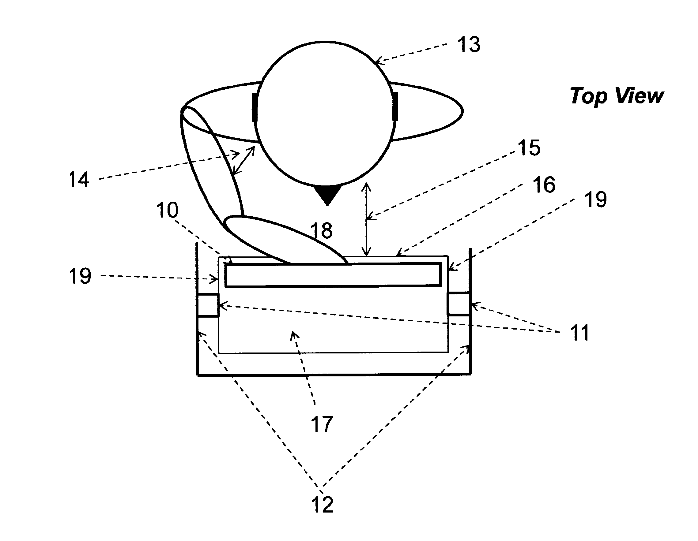
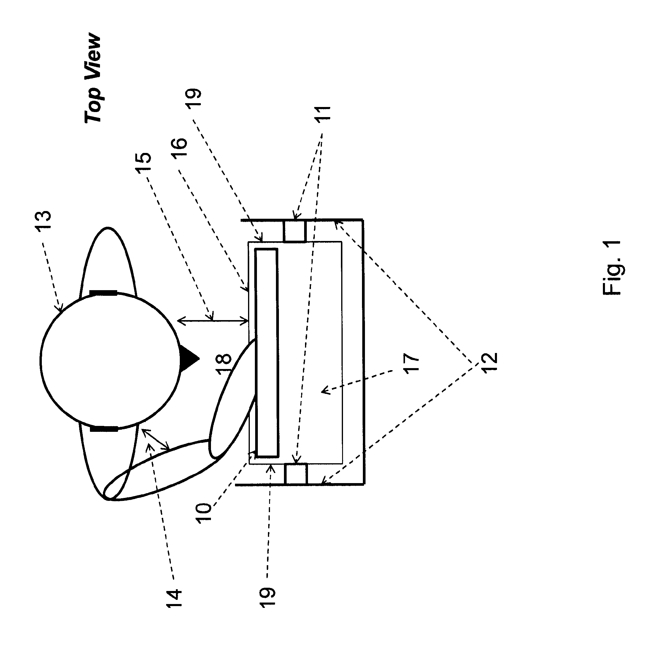
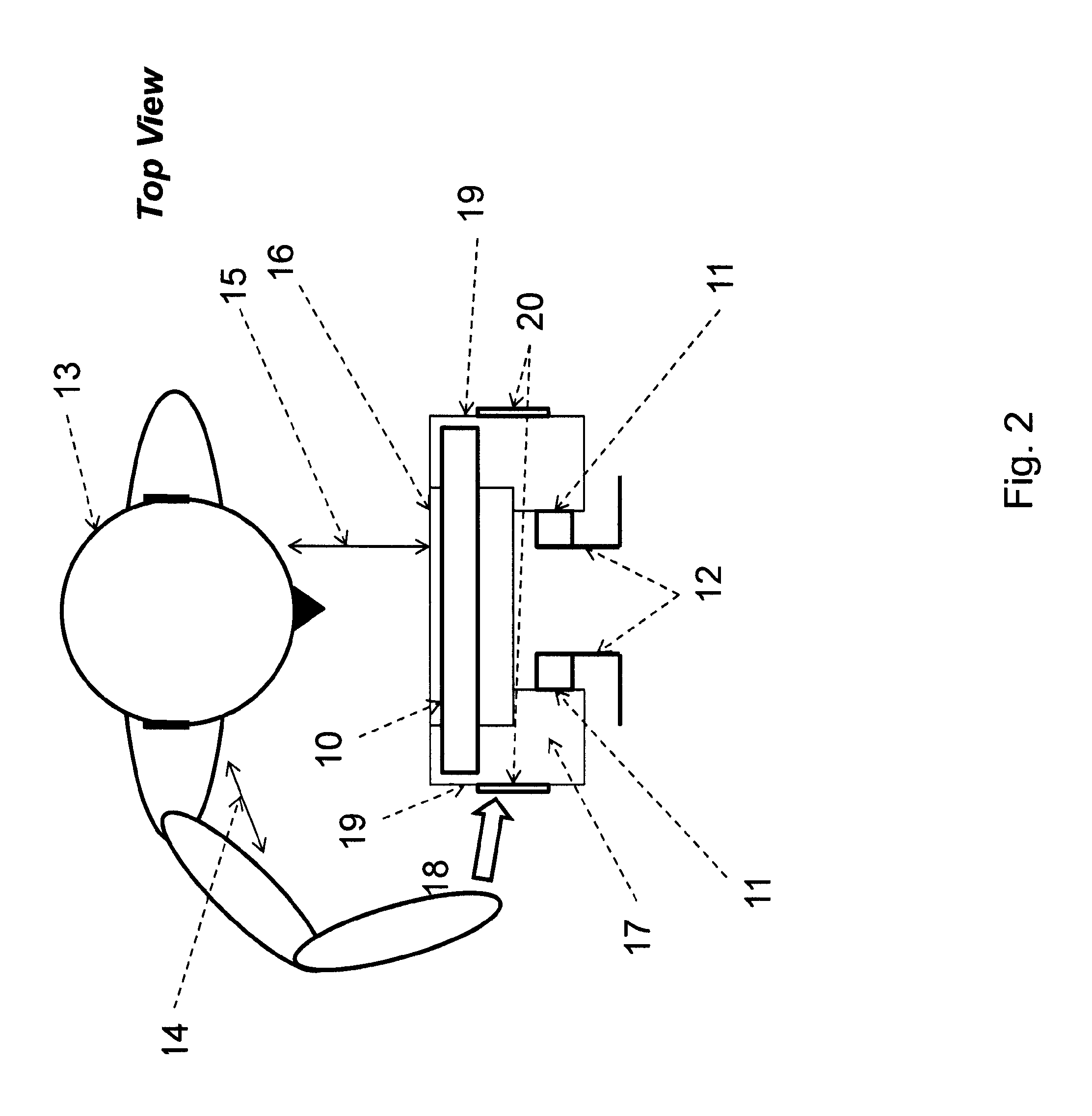
[0053]FIG. 2 shows the invention. A first assembly 17 contains a camera and illuminator module 10 and is located on horizontal pivots 11, such that the left and right sides 19 of the first assembly 17 are freely exposed to the hand 18 of the user 13 for manual up-down adjustment. More specifically, a camera and illuminator module 10 is mounted in a first assembly 17 pointed substantially at a user 13 through a front surface 16, and a pivot mechanism 11 is mounted on a second assembly for pivoting the first assembly such that one or more side surfaces 19 of the first assembly are not enclosed by the one or more sides 12 of the second assembly.

[0054]In this embodiment, the first assembly 17 surrounds the pivots 11 as shown in FIG. 2.

[0055]The first advantage of this mechanical configuration of the camera and illuminator module is that the user 13 can move their hand 18 from a wide angle from either the left or right, depending on whether the user adjusts the device with their left or ...

second embodiment

[0064]In some cases it is advantageous to avoid having the user adjust the tilt orientation of the device to minimize further the interaction of the user with the device. FIG. 10 shows this second embodiment of the invention. A camera module 101 and illuminator module 102 is located on a horizontal shaft that rotates by a position-controlled motor 100 within a housing of any type, including horizontally-oriented, cylindrical or oval-shaped, semi or fully transparent housings. Optionally, the illuminator modules may be fixed such that the only the camera module rotates. Also optionally, the camera module may be fixed but may be directed towards a mirror that is attached to the rotating shaft.

[0065]This approach of using only one degree of rotational freedom is in contrast to the pan and tilt mechanisms described by Chmielewski in U.S. Pat. No. 5,717,512 and Van Sant in U.S. Pat. No. 6,320,610. Any moving mechanism, be it pan or tilt or both, has a latency in time between the time tha...


PUM


Abstract

An iris recognition system is disclosed wherein the tilt of a camera and illuminator module is manually or automatically adjusted in a manner that is efficient and easy to use, and wherein a user guidance system provides a reflective view of the user that facilitates user-centering. The camera and / or illuminator module are preferably tiltable only about a substantially horizontal axis. The user guidance system preferably includes a reflective surface that is convex in substantially only one direction, most preferably about a horizontal axis, and substantially flat about a vertical axis.

Description

RELATED APPLICATIONS[0001]Priority is claimed from U.S. Provisional Patent Application No. 61 / 079,161, filed Jul. 9, 2008, entitled “Biometric Data Acquisition Device”, the teachings of which are incorporated by reference herein.BACKGROUND OF THE INVENTION[0002]Biometric acquisition devices are responsible for acquiring image or other data that can be used in subsequent matching algorithms for the purposes of identity verification or recognition. Biometrics in common use are face, iris and fingerprint. The performance of biometric devices is often quantified solely by the false-accept, false-reject and failure-to-acquire rates. The iris biometric performs extremely well as quantified by these metrics [J G Daugman. High confidence visual recognition of persons by a test of statistical independence. IEEE Trans. on PAMI, 15(11):1148-1161, 1993]. Iris recognition algorithms and systems have been developed (e.g. U.S. Pat. No. 4,641,349, U.S. Pat. No. 5,291,560, U.S. Pat. No. 6,594,377) h...

Claims


Application Information

Patent Timeline
Patent Type & Authority Applications(United States)
IPC IPC(8): G06K9/00
CPCG06K9/00597G06V40/19G06V10/242G06V40/18
Inventor HANNA, KEITH J.DAVILA, CARLOS A.
Owner EYELOCK
Why Eureka
Try Eureka