Thermal mass gas flow sensor and method of forming same

a gas flow sensor and gas flow sensor technology, applied in the field of flow sensors, can solve the problems of high cost, high cost, and high cost, and achieve the effects of reducing the degradation of elements by water, accelerating recovery from exposure to water, and enhancing protection

Inactive Publication Date: 2007-09-13
HONEYWELL INT INC
View PDF24 Cites 32 Cited by
  • Summary
  • Abstract
  • Description
  • Claims
  • Application Information

AI Technical Summary

Benefits of technology

[0014] By providing a fluoropolymer protective layer on the sensing and heater elements, electrochemical reaction between the elements and the water is suppressed so that degradation of the elements by the water is minimized. A substantially waterproof thermal mass gas flow meter is therefore provided. Furthermore, if the protective layer is also hydrophobic, as in the case of the PTFE layer, then protection will be enhanced and recovery from exposure to the water accelerated.

Problems solved by technology

Unfortunately, thermal mass gas flow meters, in particular thermal mass air flow sensors, are susceptible to damage caused by repeated or long term exposure to liquid resulting from condensation or immersion in liquids.
This damage is especially severe and rapid if the liquid is electrically conductive, example being impure water.

Method used


Image

  • Thermal mass gas flow sensor and method of forming same
  • Thermal mass gas flow sensor and method of forming same
  • Thermal mass gas flow sensor and method of forming same

Examples


Embodiment Construction

[0030] The particular values and configurations discussed in these non-limiting examples can be varied and are cited merely to illustrate at least one embodiment of the present invention and are not intended to limit the scope of the invention.

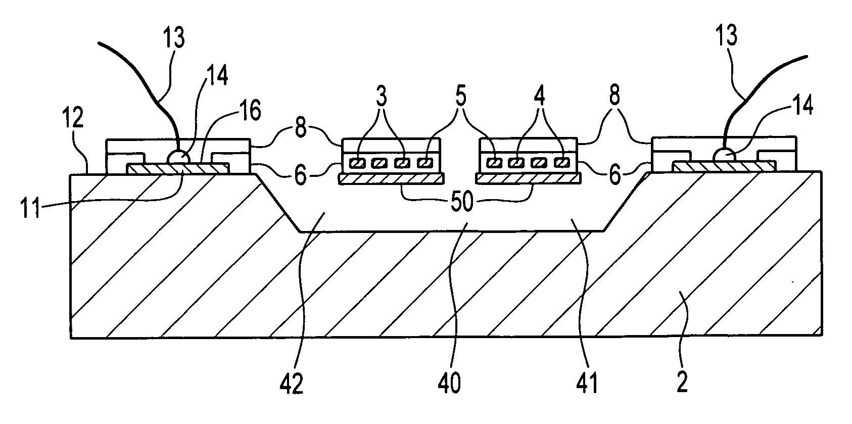
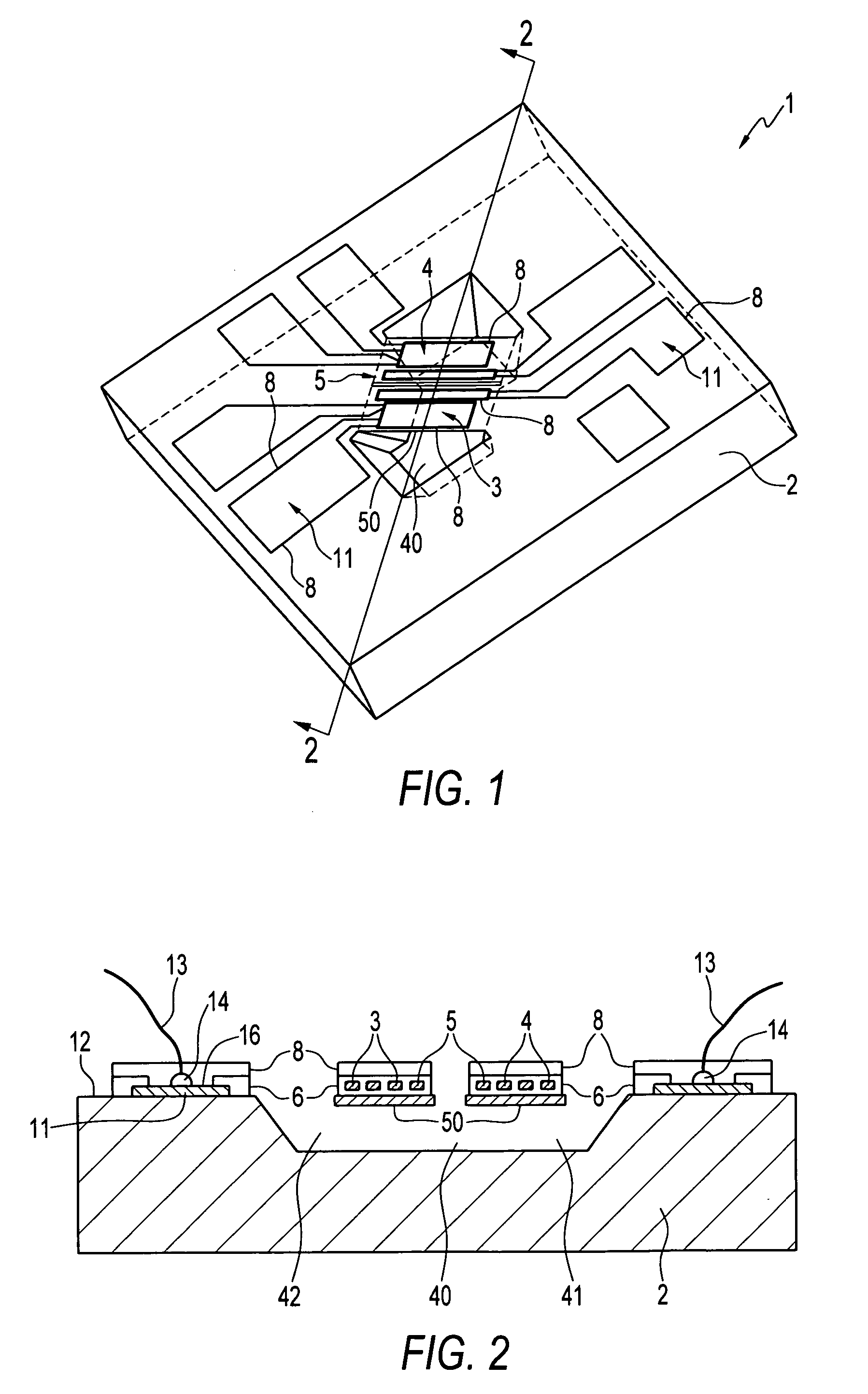
[0031] Referring to the accompanying drawings, FIG. 1 illustrates a perspective view taken from above the thermal mass gas flow sensor according to one embodiment and FIG. 2 illustrates a cross-sectional view taken along line A-A of FIG. 1 with wires bonded to the sensor. As a general overview, the thermal mass gas flow sensor 1 has a substrate 2 and a heater 5 disposed on the substrate 2 between a pair of thermal sensing elements 3, 4, also disposed on the substrate. A protective layer 8 is disposed on the heater 5 and thermal sensing elements 3, 4. The protective layer 8 is formed from a high temperature resistant insulating or dielectric layer which is preferably an organic layer such as a polymer based layer. For the reasons explained in ...


PUM

PropertyMeasurementUnit
temperaturesaaaaaaaaaa
thicknessaaaaaaaaaa
thicknessaaaaaaaaaa

Abstract

A thermal gas flow sensor and method of forming such a sensor. The sensor has a substrate and a heater disposed on the substrate. At least one pair of thermal sensing elements is disposed on the substrate either side of the heater. A protective layer is disposed on at least the heater and/or the thermal sensing elements. The protective layer comprises a high temperature resistant polymer based layer which is preferably a fluoropolymer based layer. The protective layer can also cover interconnects and electrical connections also formed on the substrate so as to completely seal the sensor. A passivation layer, such as silicon nitride, can be disposed on the sensing and/or heating elements and optionally the interconnects and is arranged to interpose the protective layer and the substrate.

Description

TECHNICAL FIELD [0001] Embodiments are generally related to flow sensors, and in particular, to thermal mass gas flow sensors, such as thermal air flow sensors, and methods of manufacturing such thermal gas flow sensors. Embodiments are additionally related to thermal gas flow sensors in the form of MEMS devices. BACKGROUND OF THE INVENTION [0002] Thermal mass gas flow sensors in the form of MEMS devices are configured to measure properties of a gas, such as air, in contact with the sensors and provide output signals representative of the gas flow rates. Thermal mass gas flow sensors are configured to heat the gas and measure the resulting thermal properties of the gas to determine flow rates. Such thermal flow sensors generally include a microsensor die consisting of a substrate and one or more elements disposed on the substrate for heating the gas and sensing the gas thermal properties. A microbridge gas flow sensor, such as the device detailed in U.S. Pat. No. 4,651,564 to Johnso...

Claims


Application Information

Patent Timeline
Patent Type & Authority Applications(United States)
IPC IPC(8): G01F1/68
CPCG01F1/692G01F1/6845
Inventor GEHMAN, RICHARD W.DMYTRIW, ANTHONY M.BLUMHOFF, CHRISTOPHER M.SHIFFER, STEPHEN R.
Owner HONEYWELL INT INC
Why Eureka
Try Eureka