Repeater system for strong signal environments

a strong signal environment and repeater technology, applied in repeater circuits, transmission monitoring, line-transmission details, etc., can solve the problem of unintentional imbalance in total losses between downlink and uplink directions, and achieve the effect of reducing co-channel interference, reducing co-channel interference, and being affordable and easy-to-install by consumers

Active Publication Date: 2006-01-31
CUFER ASSET LTD LLC
View PDF49 Cites 51 Cited by
  • Summary
  • Abstract
  • Description
  • Claims
  • Application Information

AI Technical Summary

Benefits of technology

[0020]In view of the foregoing, a broad objective of the present invention is to reduce co-channel interference in portable telephone systems. Another objective of the present invention is to reduce co-channel interference in a manner that is affordable and easily installable by a consumer. Another objective is to minimize degradation of performance of any other part of the same or other portable telephone systems.

Problems solved by technology

The repeater operates in the downlink direction between the base station and the subscriber units near the repeater and the presence of the repeater in the downlink direction causes an intentional imbalance in total losses between the downlink and the uplink directions.

Method used


Image

  • Repeater system for strong signal environments
  • Repeater system for strong signal environments
  • Repeater system for strong signal environments

Examples


Embodiment Construction

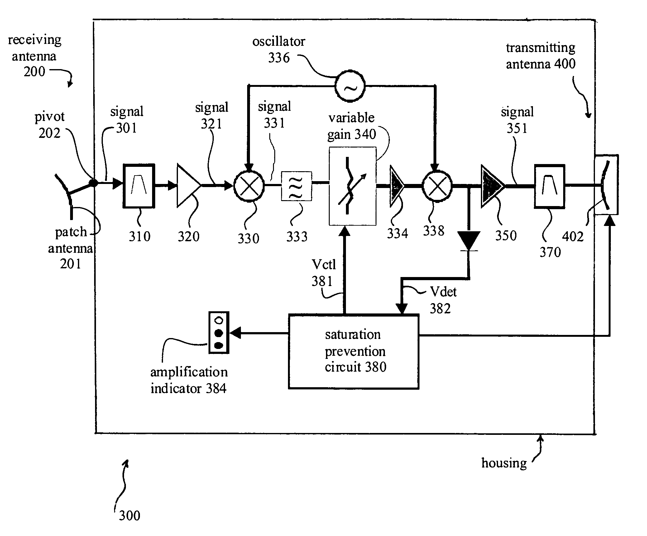
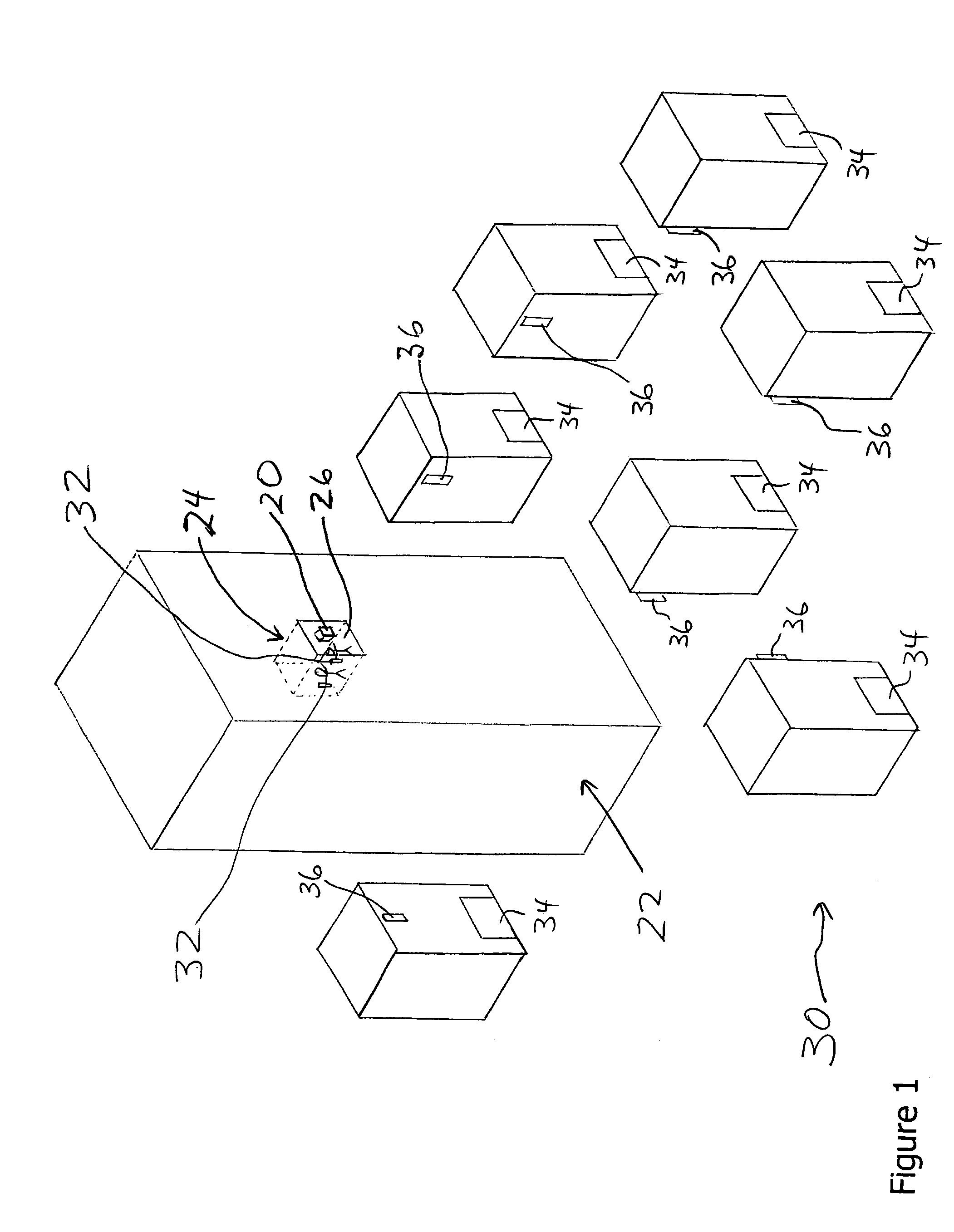
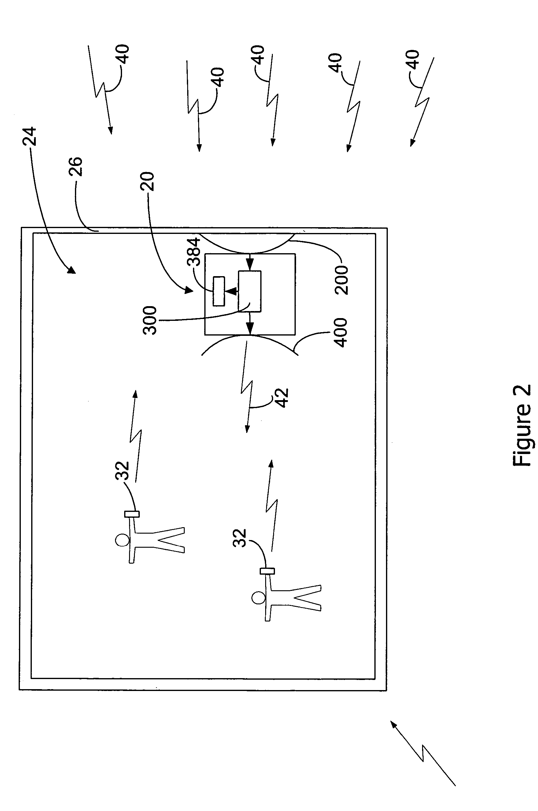
[0042]Reference will now be made to the accompanying drawings, which assist in illustrating the various pertinent features of the present invention. Although the present invention will now be described primarily in conjunction with solving pilot pollution problems in high-rise buildings, it should be expressly understood that the present invention may be applicable to other applications where a solution to co-channel interference in strong signal environments is required / desired. In this regard, the following description of a system that solves pilot pollution problems in high-rise buildings is presented for purposes of illustration and description. Furthermore, the description is not intended to limit the invention to the form disclosed herein. Consequently, variations and modifications commensurate with the following teachings, and skill and knowledge of the relevant art, are within the scope of the present invention. The embodiments described herein are further intended to explai...


PUM


Abstract

A repeater system combines co-located antennas, limited and controlled downlink signal amplification, stability management and an amplification indicator to create a user-installed solution to co-channel interference within cellular systems, in strong signal environments such as elevated locations or high-rise building. The invention may be particularly relevant to cellular systems, such as CDMA, that allow limited imbalance between uplink and downlink path losses, thus enabling the design of an inexpensive downlink repeater which creates moderate signal amplification for selected line-of-sight signals, defeating co-channel interference over a small area. Signal amplification is maintained at a level below the capacity of the system to support imbalance, guaranteeing reliable cellular calls.

Description

CROSS-REFERENCE TO RELATED APPLICATIONS[0001]This application claims priority from U.S. Provisional Patent Application No. 60 / 451,397, filed Mar. 4, 2003, entitled “Personal Repeater for Cellular Systems”, the contents of which are incorporated herein by reference.FIELD OF THE INVENTION[0002]This present invention relates generally to repeater systems for mobile communication systems such as cellular telephone systems, and more particularly to imbalanced downlink repeater systems.BACKGROUND OF THE INVENTION[0003]As is well known, cellular and PCS systems provide two-way audio and data communications to subscribers, deploying hundreds of cell sites in a typical large city to create coverage over 95% or more of the targeted area. Downlink signals are transmitted to cellular subscriber telephones from directional base station antennas mounted at 30–100 ft above ground level. Uplink signals are received from subscribers by the same directional antennas.[0004]In the United States in 2003...

Claims


Application Information

Patent Timeline
Patent Type & Authority Patents(United States)
IPC IPC(8): H04B7/15H04B7/155H04B7/26
CPCH04B7/15535H04W88/04H04B7/2606H04B7/15571
Inventor O 'NEILL, FRANK P.
Owner CUFER ASSET LTD LLC
Why Eureka
Try Eureka