Ultrasound probe, ultrasound diagnostic imaging apparatus and manufacturing method of ultrasound probe

a manufacturing method and ultrasound technology, applied in diagnostics, mechanical vibration separation, medical science, etc., can solve the problems of reduced inability to generate desired ultrasound stably, and easy cracks in the bonding surface, so as to improve the advantageous effect, reduce the advantageous effect of composite piezoelectric layer, and improve the advantageous effect

Active Publication Date: 2014-08-07
KONICA MINOLTA INC
View PDF3 Cites 24 Cited by
  • Summary
  • Abstract
  • Description
  • Claims
  • Application Information

AI Technical Summary

Benefits of technology

[0011]However, in the technique described in JP 2009-61112, there is a problem that the advantageous effect as a composite piezoelectric layer is reduced because the piezoelectric material is not cut out to the bonding surface with the acoustic reflection layer. Therefore, in order to improve the advantageous effect, it is necessary to cut out the piezoele...

Problems solved by technology

However, in the technique described in JP 2009-61112, there is a problem that the advantageous effect as a composite piezoelectric layer is reduced because the piezoelectric material is not cut out to the bonding surface with the ...

Method used


Image

  • Ultrasound probe, ultrasound diagnostic imaging apparatus and manufacturing method of ultrasound probe
  • Ultrasound probe, ultrasound diagnostic imaging apparatus and manufacturing method of ultrasound probe
  • Ultrasound probe, ultrasound diagnostic imaging apparatus and manufacturing method of ultrasound probe

Examples


Embodiment Construction

[0037]Hereinafter, an ultrasound probe 1 and an ultrasound diagnostic imaging apparatus 2 according to the present invention will be described with reference to the drawings.

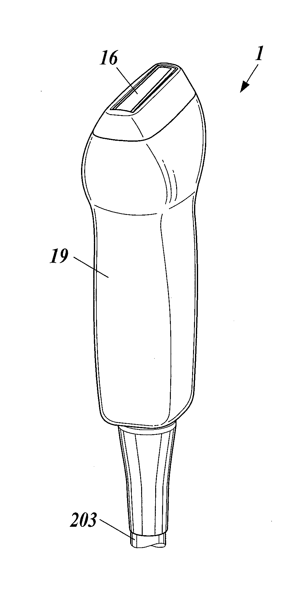
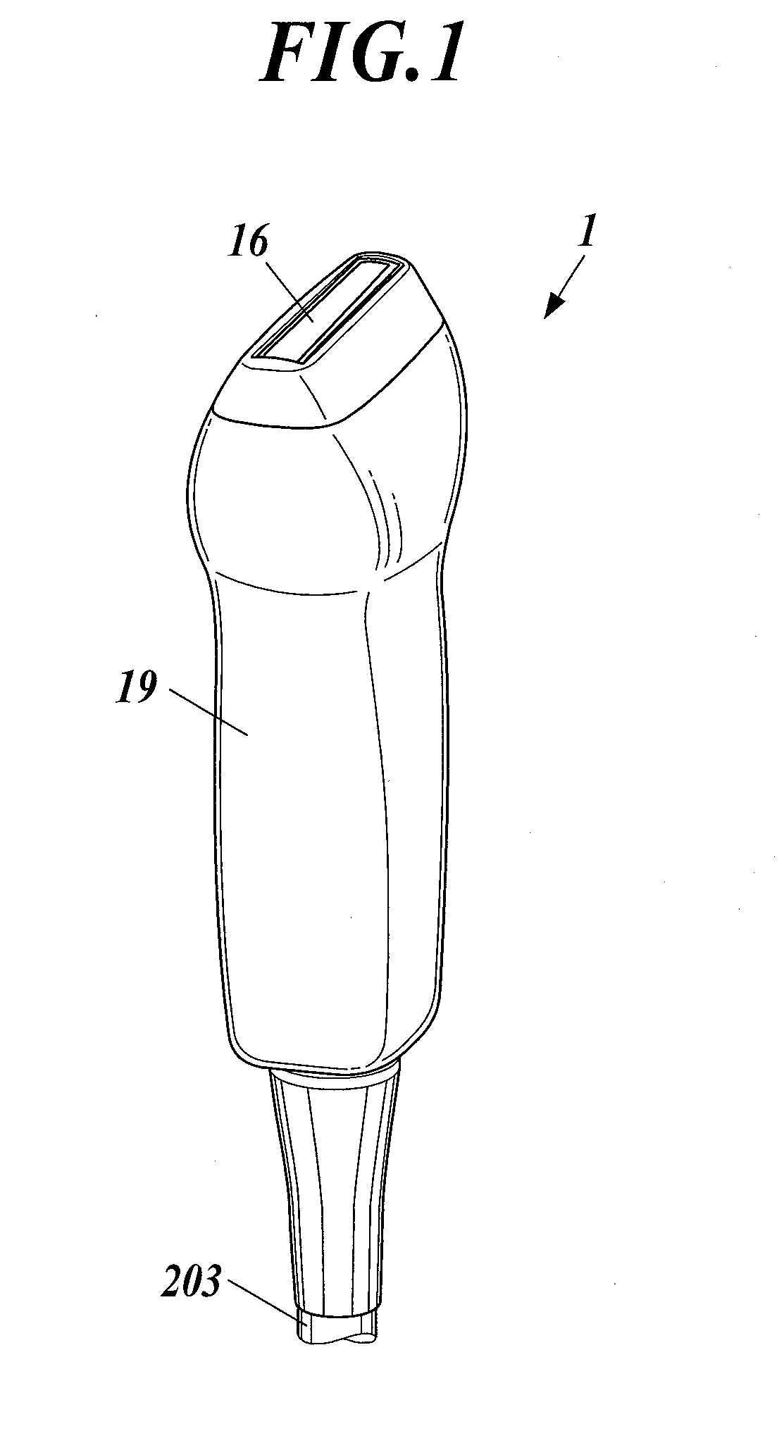
[0038]FIG. 1 shows an outer configuration of the ultrasound probe 1 according to the embodiment. The ultrasound probe includes an acoustic lens 16 which makes direct contact with a subject, a case holding unit 19 and a cable 203.

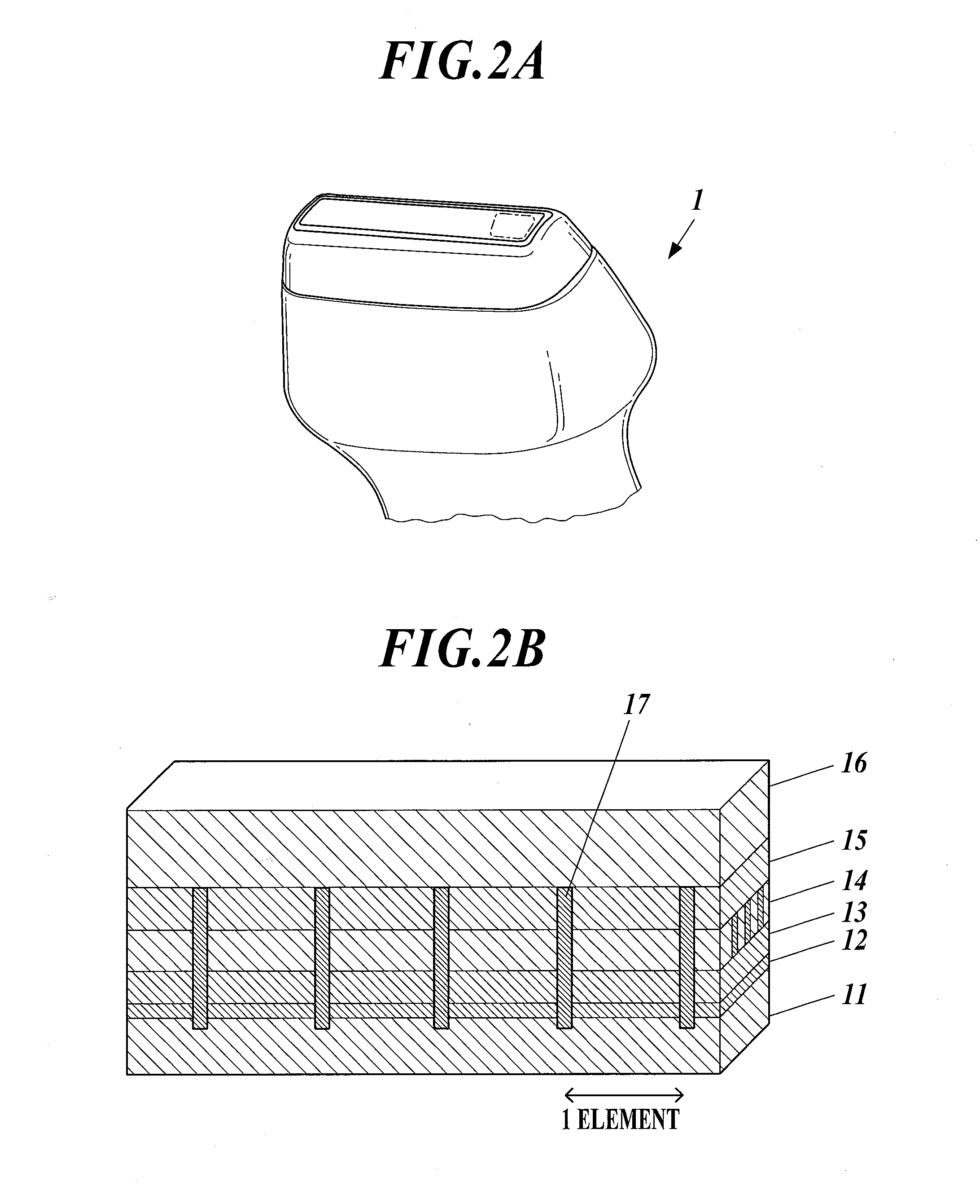
[0039]FIG. 2A shows a part of the outer configuration of the ultrasound probe 1. FIG. 2B is a schematic sectional view of the portion indicated by dot-dash-line in the ultrasound probe 1 shown in FIG. 2A. The ultrasound probe 1 of the embodiment includes, layered from the bottom, a backing layer 11, a flexible printed board 12, an acoustic reflection layer 13, a composite piezoelectric layer 14 which is configured of a piezoelectric material 14a and a polymer material 14b being integrated, an acoustic matching layer 15 and an acoustic lens 16, and the layers are joined to each other by a...


PUM


Abstract

Disclosed is an ultrasound probe which outputs ultrasound on a basis of a drive signal which is to be received. The ultrasound probe including a composite piezoelectric layer in which a piezoelectric material and a polymer material are arranged alternately in a one-dimensional array or in a two-dimensional array, an acoustic reflection layer which has an acoustic impedance higher than an acoustic impedance of the composite piezoelectric layer and an adhesion layer which bonds the composite piezoelectric layer and the acoustic reflection layer wherein in a bonding surface of the composite piezoelectric layer that bonds with the acoustic reflection layer, a polymer material part is concaved in a direction opposite to an acoustic reflection layer side comparing to an piezoelectric material part.

Description

BACKGROUND OF THE INVENTION[0001]1. Field of the Invention[0002]The present invention relates to an ultrasound probe which includes a composite piezoelectric layer which realizes high sensitivity and wider bandwidth, an ultrasound diagnostic imaging apparatus and a manufacturing method of the ultrasound probe.[0003]2. Description of Related Art[0004]Ultrasound diagnostic imaging apparatuses of high image quality are desired, and making ultrasound probes realize high sensitivity and wider bandwidth is suggested as a method for realizing high image quality.[0005]An ultrasound probe makes an piezoelectric material excite elastic vibration whose thickness corresponds to ¼) and emits ultrasound generated by the elastic vibration to a subject. With respect to the ultrasound energy emitted in the direction opposite to the direction in which a subject is positioned, since the ultrasound is reflected in the direction opposite to the direction toward a subject by an acoustic reflection layer ...

Claims


Application Information

Patent Timeline
IPC IPC(8): A61B8/00
CPCA61B8/4444A61B8/4405A61B8/4483B06B1/0622B06B1/0677
Inventor OKUDA, SHUHEI
Owner KONICA MINOLTA INC
Why Eureka
Try Eureka