
Dual-shaft synchronous motion device

a synchronous motion and dual-shaft technology, applied in the direction of hinges, wing accessories, instruments, etc., can solve the problems that the above-mentioned patents don't teach or disclose these topics

Active Publication Date: 2014-08-14
FIRST DOME
View PDF18 Cites 28 Cited by
  • Summary
  • Abstract
  • Description
  • Claims
  • Application Information

AI Technical Summary

Benefits of technology

The invention is a synchronous motion device that allows the display module and the machine body module to move in unison when the operator only operates the display module. This allows the user to achieve a full 360-degree turning angle of the display module and the machine body module by only having to turn the display module. This easy-to-use device makes it convenient for users to operate the electronic product in different modes.

Problems solved by technology

The aforesaid patents don't teach or disclose these topics.

Method used


Image

  • Dual-shaft synchronous motion device
  • Dual-shaft synchronous motion device
  • Dual-shaft synchronous motion device

Examples


Embodiment Construction

[0024]Embodiments of the present invention will now be described, by way of example only, with reference to the accompanying drawings.

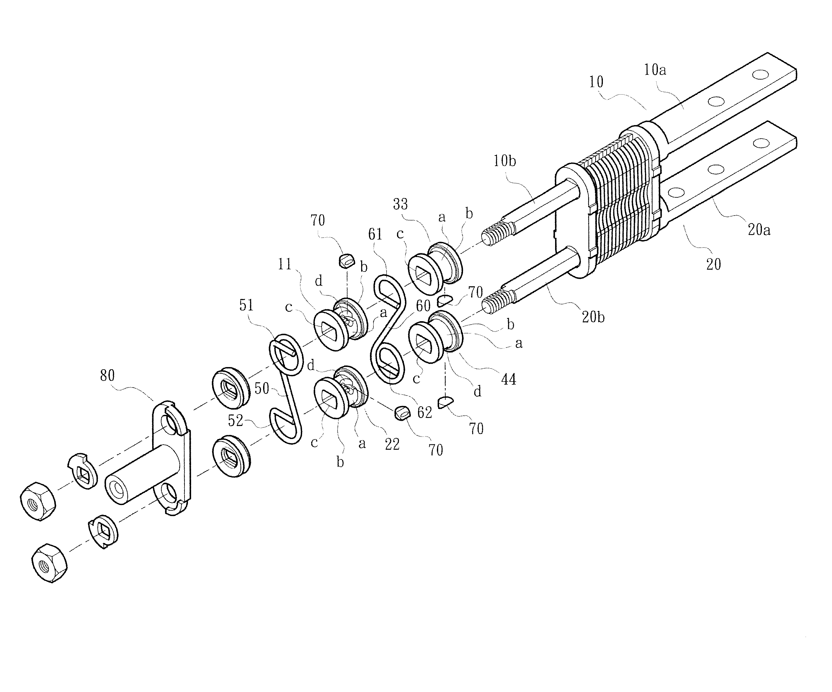
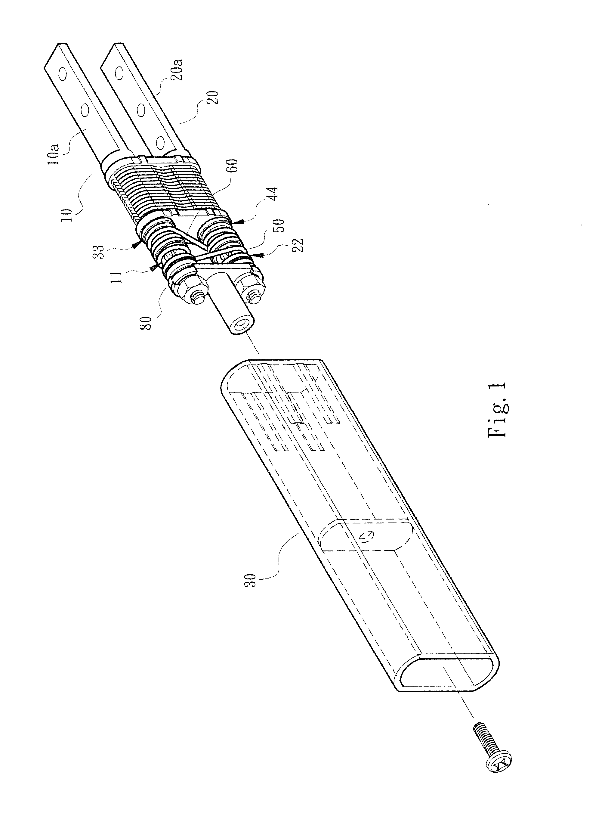
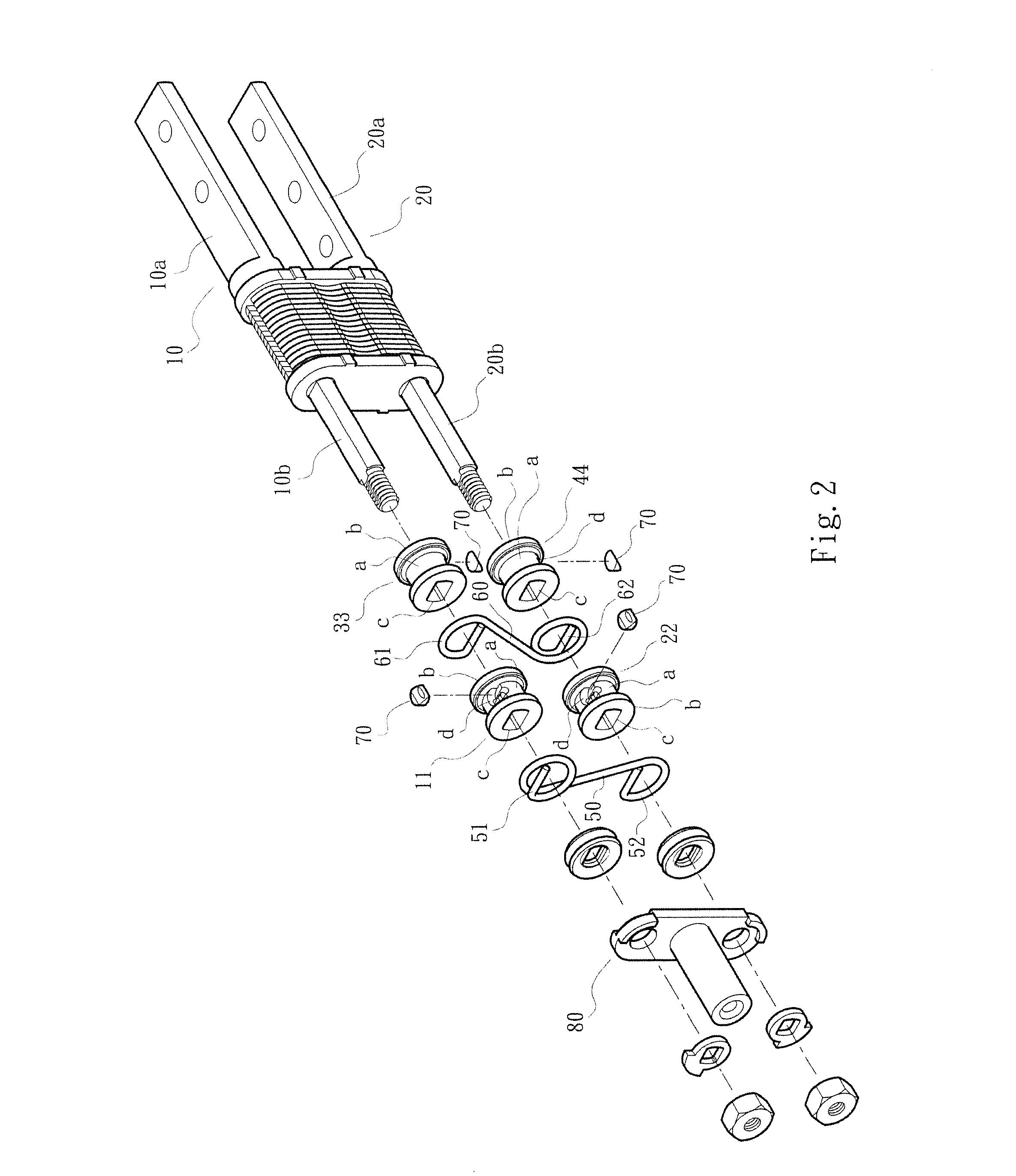
[0025]As shown in FIG. 1, FIG. 2 and FIG. 3, the dual-shaft synchronous motion device of the present invention comprises a first shaft 10 and a second shaft 20. The first shaft 10 and the second shaft 20 are mounted in a casing 30. The first and second shafts 10, 20 respectively have a fixed end 10a, 20a and a pivot end 10b, 20b. The fixed ends 10a, 20a cooperate with a fixed seat (not shown in the drawings), so that the first and second shafts 10, 20 are fixed to a display module 91 and a machine body module 92 of an electronic article 90, such as a cell phone, a computer or the like.

[0026]As shown in FIG. 1, FIG. 2 and FIG. 3, the pivot end 10b of the first shaft 10 comprises a first rotor 11 and a third rotor 33 which can be turned synchronously. The pivot end 20b of the second shaft 20 comprises a second rotor 22 and a fourth rotor 44 which can be...


PUM


Abstract

A dual-shaft synchronous motion device includes a first shaft and a second shaft; a first rotor and a third rotor disposed on the first shaft and turned synchronously; a second rotor and a fourth rotor disposed on the second shaft and turned synchronously; and a tractive member disposed between the first rotor (the third rotor) and the second rotor (the fourth rotor). When the first shaft drives the first and third rotors to turn, the tractive member brings the second rotor to turn reversely relative to the first rotor. The fourth rotor makes the tractive member drive the third rotor so that the first and second shafts are turned synchronously.

Description

BACKGROUND OF THE INVENTION[0001]1. Field of the Invention[0002]The present invention relates to a dual-shaft synchronous motion device, and more particularly to a pivot shaft in cooperation with rotors and tractive members so that first and second shafts are turned synchronously.[0003]2. Description of the Prior Art[0004]A pivot or a turning shaft which can be turned back and forth by applying an external is widely used to en electronic article, such as a cell phone, a notebook, a PDA, a digital camera, an electronic book and the like, so that its cover, display screen, or a watch window can be turned to open / close. For example, Taiwan Patent No. 97222022 discloses a turning shaft structure; Taiwan Patent No. 96217011 discloses a pivot positioning structure; and Taiwan Patent No. 98207366 discloses a pivot structure.[0005]For the display module (such as, a screen) and / or the machine body module of the electronic article to provide more operation modes and applied range, the prior a...

Claims


Application Information

Patent Timeline
Patent Type & Authority Applications(United States)
IPC IPC(8): E05D3/06
CPCE05D3/06G06F1/1681E05Y2999/00
Inventor HSU, AN SZU
Owner FIRST DOME
Features
  • Generate Ideas
  • Intellectual Property
  • Life Sciences
  • Materials
  • Tech Scout
  • Unparalleled Data Quality
  • Higher Quality Content
  • 60% Fewer Hallucinations
Learn More