Selective One-Way Wrench

a one-way wrench and selective technology, applied in the field of selective one-way wrenches, can solve the problems of not being able to release the tightened nut from the screw, failing to tighten the nut on the screw, and the conventional ratchet wrench suffers a serious drawback, so as to achieve easy switching and transmit high torque

Inactive Publication Date: 2014-08-14
JIN XIANG KAI IND
View PDF7 Cites 1 Cited by
  • Summary
  • Abstract
  • Description
  • Claims
  • Application Information

AI Technical Summary

Benefits of technology

[0007]It is the primary objective of the present invention to provide a selective one-way wrench that is easily switchable between two modes for transmitting high torque.

Problems solved by technology

This conventional ratchet wrench however suffers a serious drawback.
That is, it fails to tighten a nut on a screw or release a tightened nut from a screw.

Method used


Image

  • Selective One-Way Wrench
  • Selective One-Way Wrench
  • Selective One-Way Wrench

Examples


Embodiment Construction

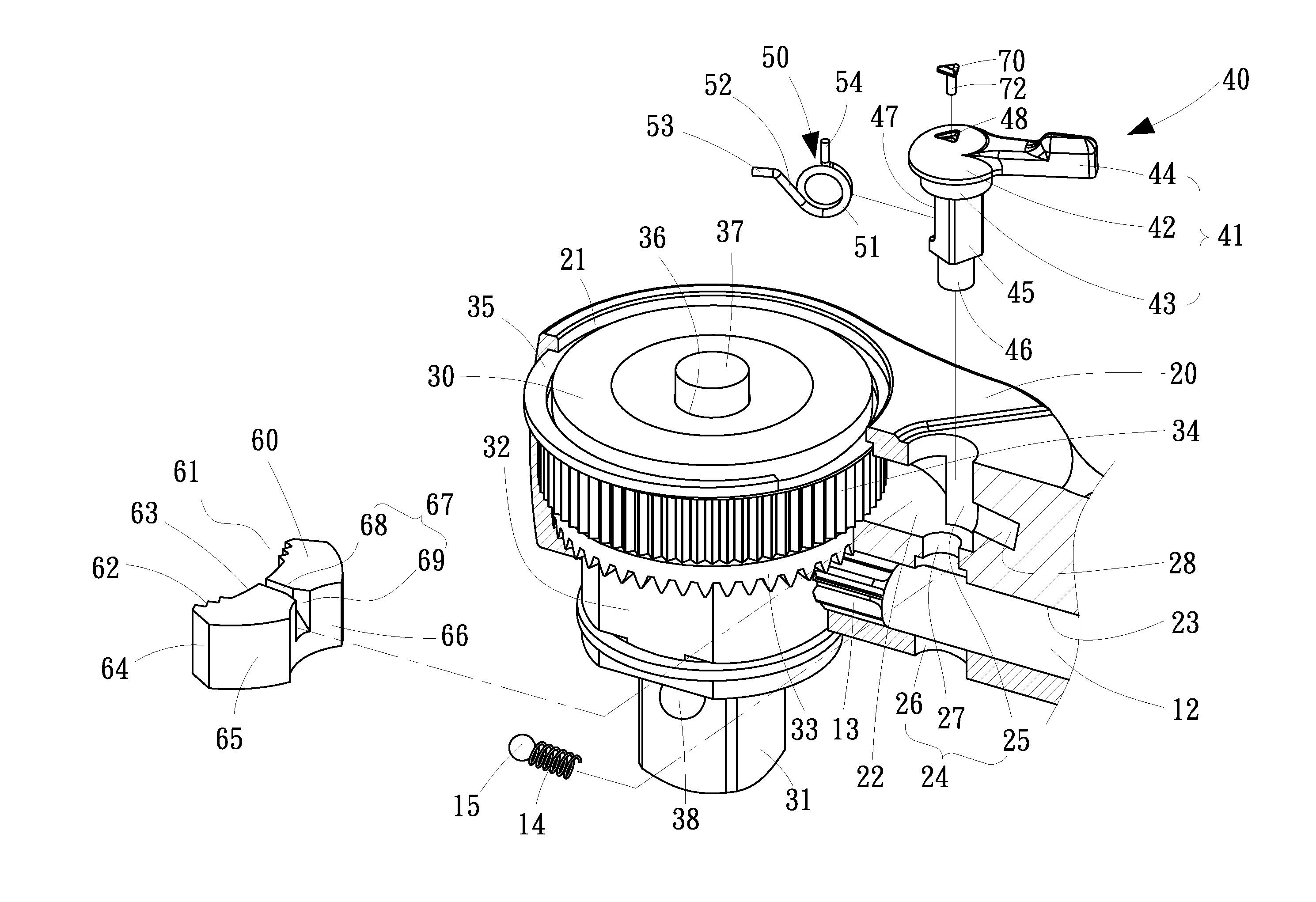
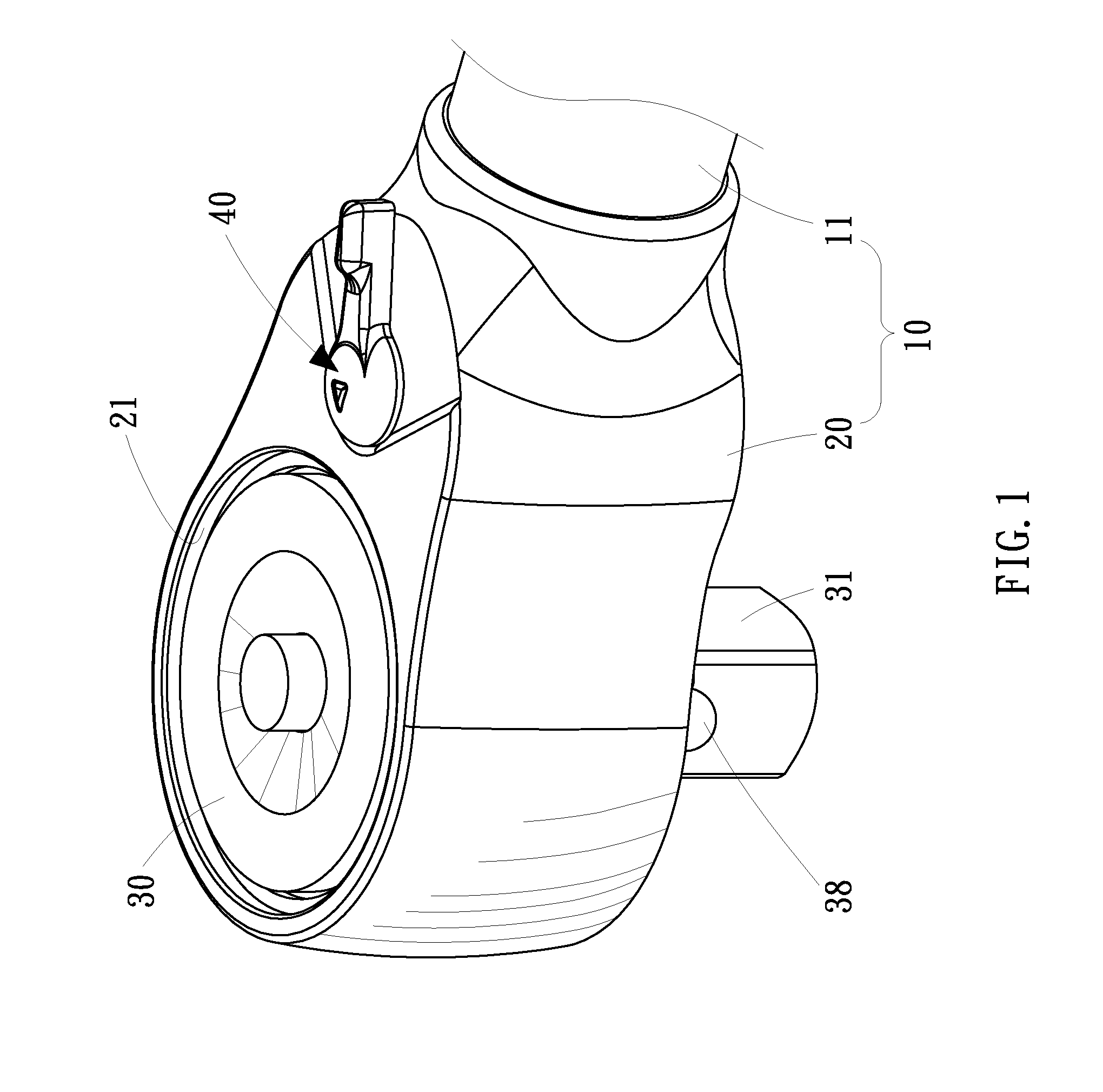
[0018]Referring to FIG. 1, a selective one-way wrench 10 according to the preferred embodiment of the present invention is shown. The wrench 10 includes a handle 11, a head 20, a rotor 30 and a mode-switching unit 40. The handle 11 extends from the head 20. The handle 11 includes an axial bore 23 for receiving an axle 12. A pinion 13 is formed at an end of the axle 12.

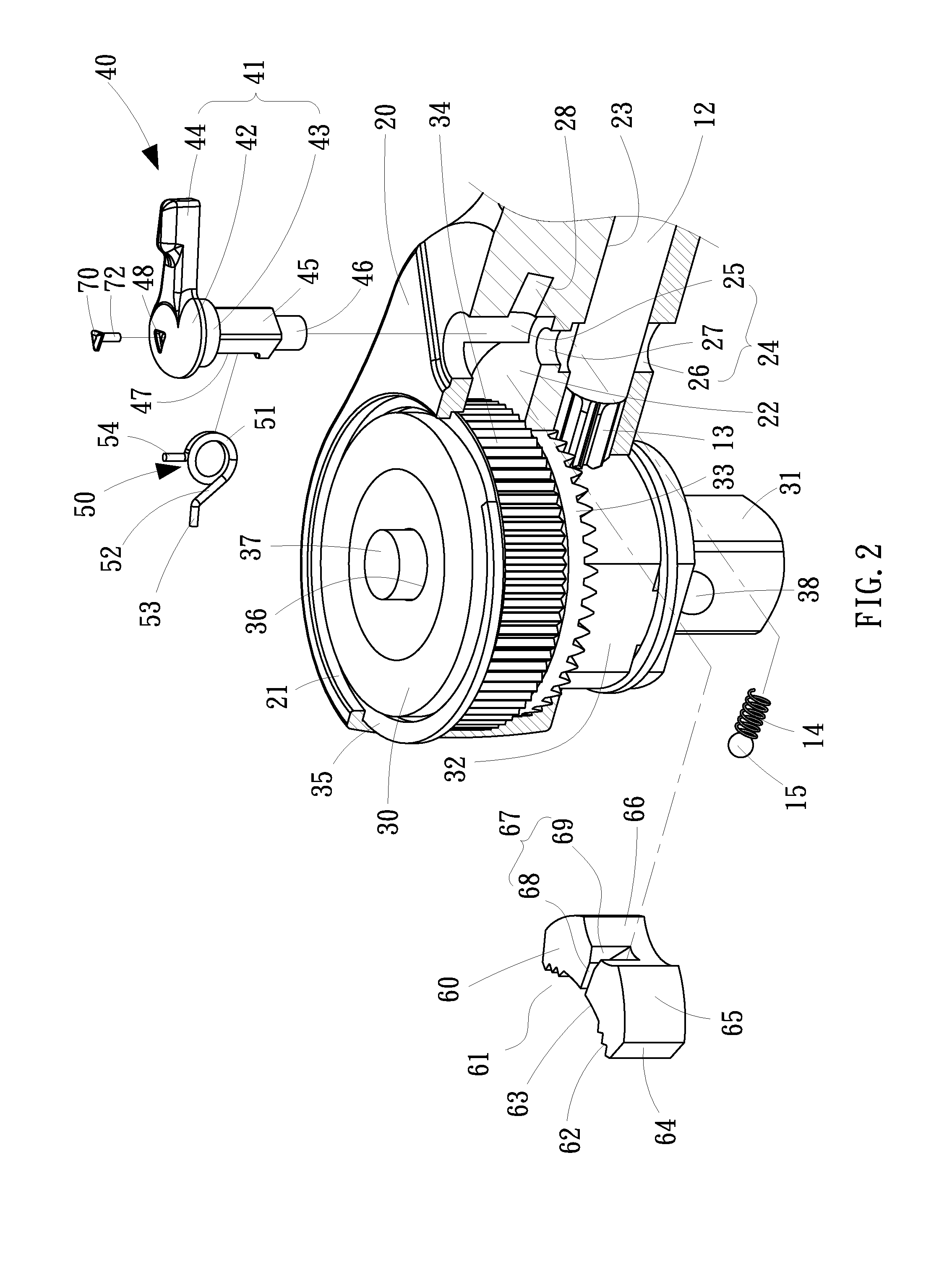
[0019]Referring to FIG. 2, the head 20 is a hollow element that includes three cavities 21, 22 and 24 and a bore 28. The cavities 21 and 24 are substantially circular cavities. The cavity 22 is a substantially crescent cavity between and in communication with the cavities 21 and 24. The cavity 24 includes an upper portion 25, a lower portion 26 and a middle portion 27. The bore 28 is a circular bore in communication with the upper portion 25 of the cavity 24. The axis of the bore 28 intersects the axes of the cavities 21, 22 and 24 that extend parallel to one another.

[0020]The rotor 30 includes an insert 31, a block 32...


PUM


Abstract

A selective one-way wrench includes a head, a rotor, a switch, a pawl and a torque spring. The head includes a first cavity defined therein, a second cavity in communication with the first cavity, and a third cavity in communication with the second cavity. The rotor is rotationally placed in the first cavity and formed with a gear. The switch includes a body pivotally inserted in the third cavity, a recess defined in the body, and a bore in communication with the recess. The pawl is movably placed in the second cavity and formed with a plurality of teeth engaged with the gear and a groove defined therein. The torque spring includes a helical portion placed in the recess, a first rectilinear end extending into the groove from the helical portion, and a second rectilinear end extending into the bore from the helical portion.

Description

BACKGROUND OF INVENTION[0001]1. Field of Invention[0002]The present invention relates to a selective one-way wrench and, more particularly, to a selective one-way wrench that is easily switchable between two modes for transmitting high torque.[0003]2. Related Prior Art[0004]As disclosed in U.S. Pat. No. 1,957,462, a conventional ratchet wrench includes a body member 20, a toothed wheel 24, a pawl 25, a plunger 41, a spring 42 and a manipulator 46. The body member 20 includes a handle 21 extending from a head 22. The head 22 includes two recesses 23 and 26 in communication with each other. The toothed wheel 24 is rotationally placed in the recess 23. The toothed wheel 24 is formed with a non-cylindrical portion 34 for insertion in a socket so that the socket is rotatable together with the toothed wheel 24. The pawl 25 is movably placed in the recess 26 and formed with two pairs of teeth 40 on a side and two recesses 44 separated from each other by a protuberance 45 on an opposite sid...

Claims


Application Information

Patent Timeline
Patent Type & Authority Applications(United States)
IPC IPC(8): B25B13/46
CPCB25B13/463
Inventor LIN, DA-SEN
Owner JIN XIANG KAI IND
Why Eureka
Try Eureka