Continuous Multi-Fluid Delivery System and Method

a multi-fluid, continuous technology, applied in the direction of positive displacement liquid engines, liquid fuel engines, instruments, etc., can solve the problems of inherently limiting the pressure capability of the system to approximately 200 psi, the pump platform is typically limited to pumping a single fluid type, and the need to refill and replace disposable syringes

Inactive Publication Date: 2014-08-14
BAYER HEALTHCARE LLC
View PDF19 Cites 77 Cited by
  • Summary
  • Abstract
  • Description
  • Claims
  • Application Information

AI Technical Summary

Benefits of technology

[0011]This disclosure presents exemplary embodiments of a fluid pump device for association with a drive and actuating system, exemplary embodiments of the drive and actuating system, and exemplary embodiments of a fluid delivery system comprising the drive and actuating system and fluid pump device, as well as methods of assembling the fluid pump device and methods of operating one or more embodiments of the fluid pump device, drive and actuating system, and fluid delivery system. In one embodiment, a fluid pump device comprises a plurality of pump cylinders, a plunger reciprocally operable within each of the pump cylinders, and an inlet selector valve to establish selective fluid communication between at least one fluid source and the pump cylinders. The inlet selector valve may be located laterally outboard of the pump cylinders.

Problems solved by technology

One limitation of a syringe-based fluid injection system is the need to refill and replace the disposable syringes prior to each patient procedure.
While this system eliminates the need to replace disposable syringes after each patient, the use of a roller-type peristaltic pump inherently limits the pressure capability of the system to approximately 200 psi.
Unfortunately, many CT procedures and virtually all angiographic procedures require fluid to be delivered at higher pressures.
There are several disadvantages present in positive displacement pump platforms known in the medical field for fluid delivery to a patient.
One disadvantage is that these pump platforms are, typically, limited to pumping a single fluid type.

Method used


Image

  • Continuous Multi-Fluid Delivery System and Method
  • Continuous Multi-Fluid Delivery System and Method
  • Continuous Multi-Fluid Delivery System and Method

Examples


Embodiment Construction

[0119]For purposes of the description hereinafter, spatial orientation terms, as used, shall relate to the referenced embodiment as it is oriented in the accompanying drawing figures or otherwise described in the following detailed description. However, it is to be understood that the embodiments described hereinafter may assume many alternative variations and configurations. It is also to be understood that the specific components, devices, features, and operational sequences illustrated in the accompanying drawing figures and described herein are simply exemplary and should not be considered as limiting.

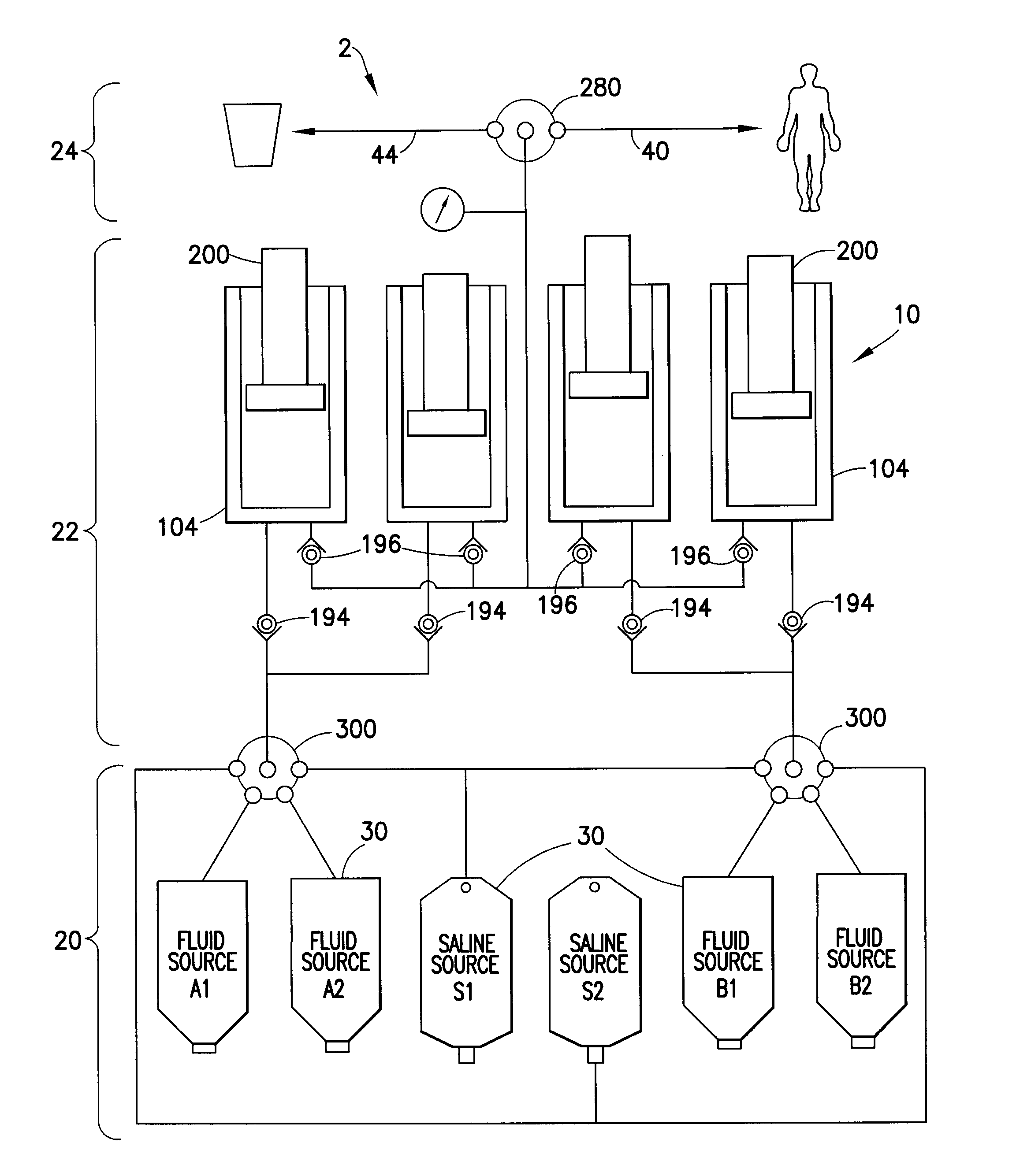
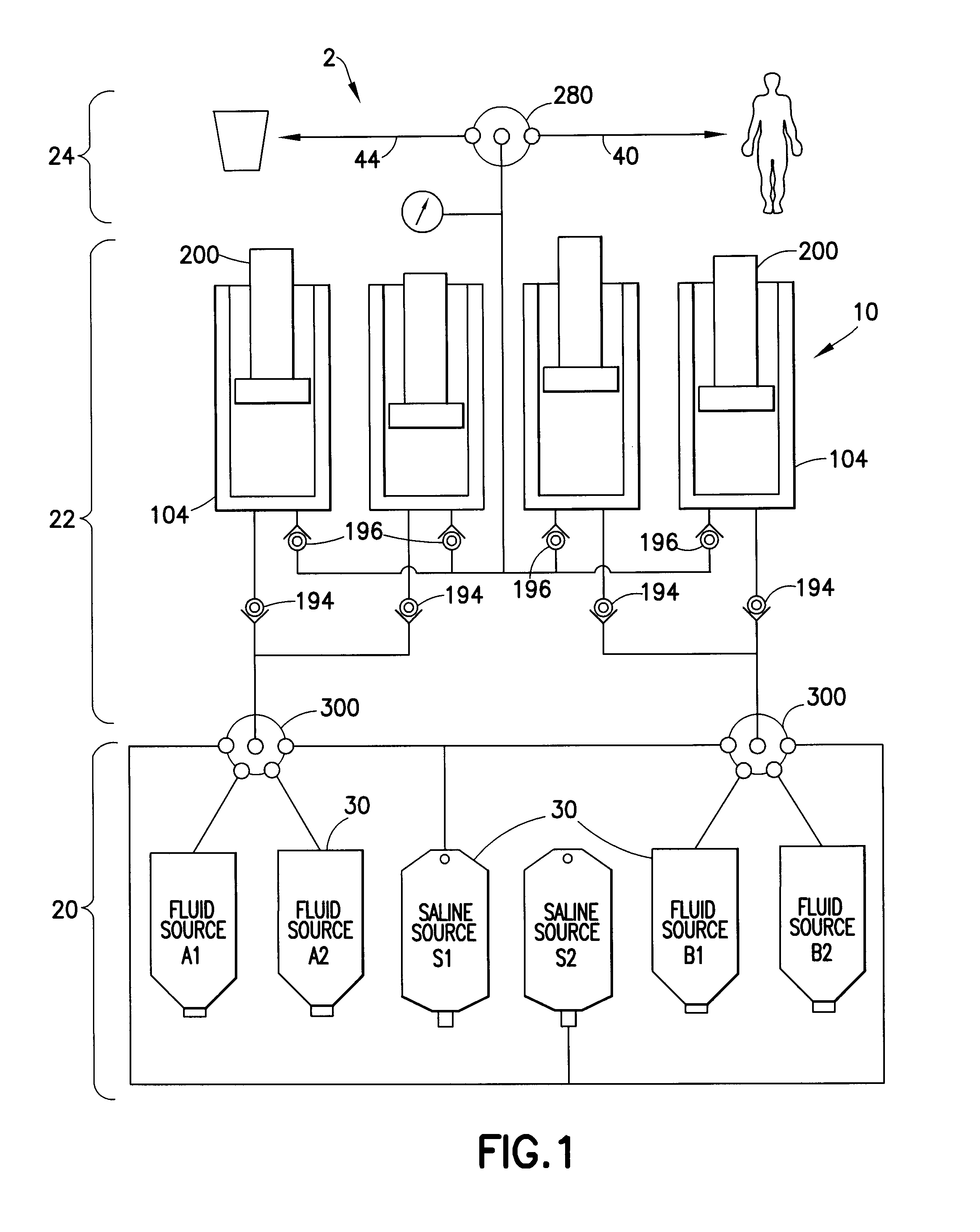
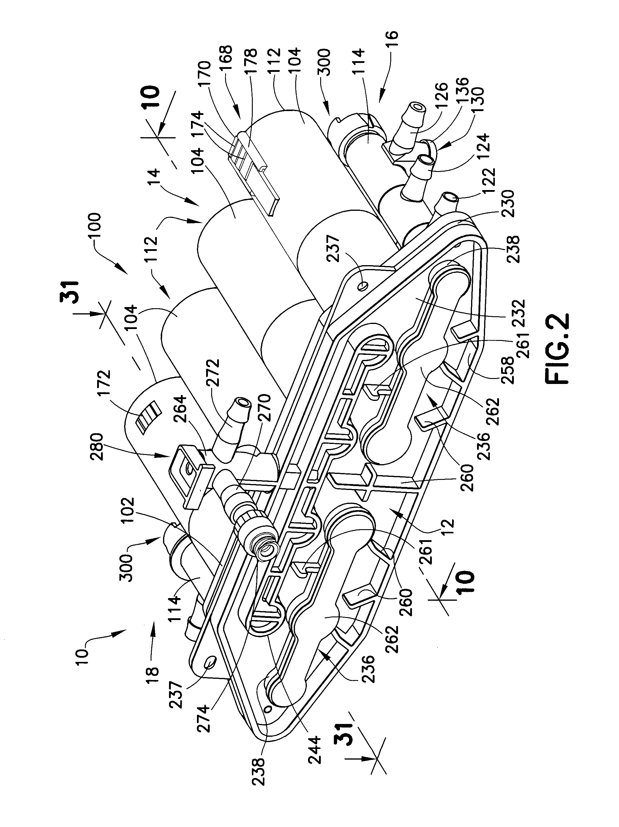
[0120]Referring initially to FIGS. 1-6, a fluid pump device 10, generally provided in the form of a disposable pump cassette, is shown. While fluid pump device or pump cassette 10 (hereinafter referred to as “pump 10”) is intended as a disposable component, the pump 10 is intended for multiple uses prior to disposal. Such multiple uses may be for multiple patients or for a multiple...


PUM

PropertyMeasurementUnit
pressure capabilityaaaaaaaaaa
pressureaaaaaaaaaa
pressureaaaaaaaaaa

Abstract

A fluid pump device is operable by a drive and actuating system. The fluid pump device includes a pump manifold, a plurality of pump cylinders, a plunger reciprocally operable in each of the pump cylinders, and at least one inlet selector valve. The pump cylinders may extend proximally from the pump manifold and are in selective fluid communication with the pump manifold via, for example, respective inlet and outlet check valves. The plungers are reciprocally operable within the pump cylinders and are independently and reciprocally operable by respective piston linear actuators provided in the drive and actuating system. The inlet selector valve is used to establish selective fluid communication between one or more fluid source containers and the pump manifold to control fluid flow into the pump manifold. The inlet selector valve may be located laterally outboard of the pump cylinders and extend generally parallel to the pump cylinders.

Description

CROSS-REFERENCE TO RELATED APPLICATIONS[0001]This application claims the benefit of U.S. Provisional Application No. 61 / 537,371, filed Sep. 21, 2011 and entitled “Continuous Multi-Fluid Delivery System and Method”, and which is incorporated herein in its entirety.BACKGROUND OF THE INVENTION[0002]1. Field of the Invention[0003]The invention described herein is directed to a fluid delivery system comprising a fluid pump device and an associated drive and actuating system for continuous multi-fluid delivery applications in medical diagnostic and therapeutic procedures wherein one or more fluids are infused / injected into a patient.[0004]2. Description of Related Art[0005]In the medical field, fluid delivery devices used to provide fluids to patients are generally well-known and exist in many different forms. A system commonly used for this purpose is a gravity-feed system wherein a fluid containing bag is supported above the level of the patient's body and wherein the flow rate to the p...

Claims


Application Information

Patent Timeline
Patent Type & Authority Applications(United States)
IPC IPC(8): B05B11/00
CPCB05B11/3015A61M5/007A61M5/1408A61M5/1422A61M5/16881A61M39/223B23P15/001F04B49/06F04B49/065F04B49/22F04B53/16F16K11/07G05D7/0635A61M2039/229A61M2207/00A61M2205/50A61M2205/6063A61M5/1452B05B11/1015Y10T29/49229Y10T137/86879Y10T29/49236Y10T29/49412Y10T29/5191A61M5/142
Inventor CAPONE, CHRISTOPHER D.SEMAN, RICHARD A.HAURY, JOHN A.PREM, EDWARD K.BISEGNA, JOSEPH E.HELLER, RONALDWILLIAMS, GLEN P.MATOR, JOSEPH C.BAZALA, JASON L.
Owner BAYER HEALTHCARE LLC
Why Eureka
Try Eureka