Transformer based sensor arrangement

a sensor arrangement and transformer technology, applied in the field of transformer based sensor arrangement, can solve problems such as peak interference with information transmitted

Active Publication Date: 2014-08-14
HAMILTON SUNDSTRAND CORP
View PDF10 Cites 16 Cited by
  • Summary
  • Abstract
  • Description
  • Claims
  • Application Information

AI Technical Summary

Problems solved by technology

If information is transmitted at, or close to, the resonance fre

Method used


Image

  • Transformer based sensor arrangement
  • Transformer based sensor arrangement
  • Transformer based sensor arrangement

Examples


Embodiment Construction

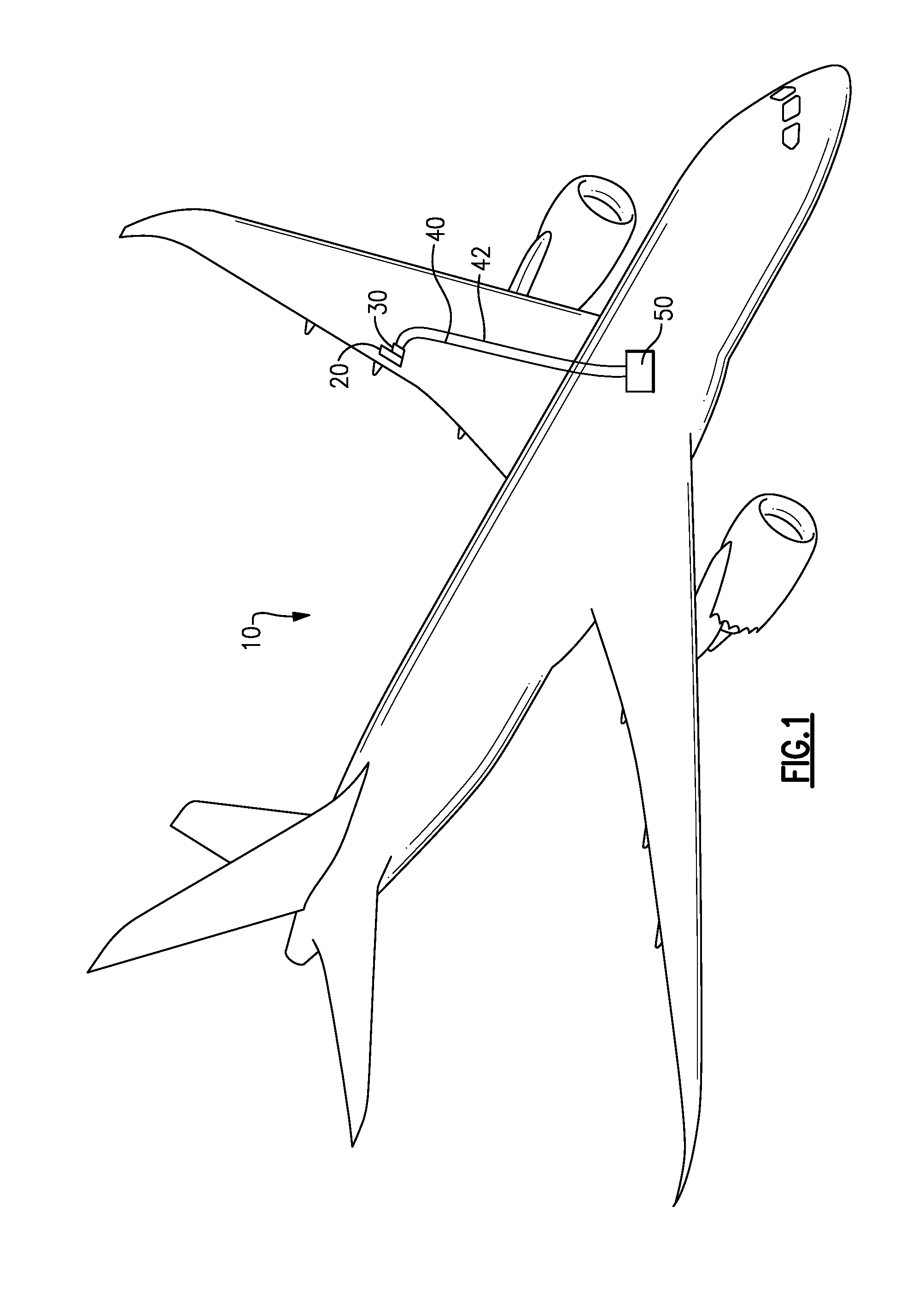
[0016]FIG. 1 illustrates an example aircraft 10 including an actuator 20. Connected to the actuator 20 is a transformer based sensor 30. In some examples, the sensor 30 is a linear variable differential transformer, a rotary variable differential transformer, or a resolver. The transformer based sensor 30 is connected to a processing system 50, such as an aircraft controller, via two sensor cables 40, 42. The processing system 50 determines the position of the actuator based on the relative amplitudes of the two sensor cables 40, 42, and utilizes the determined information to control the actuator 20. The transformer based sensor 30 introduces an inductance to the sensor arrangement resulting in a resistance-inductance (RL) based sensor arrangement.

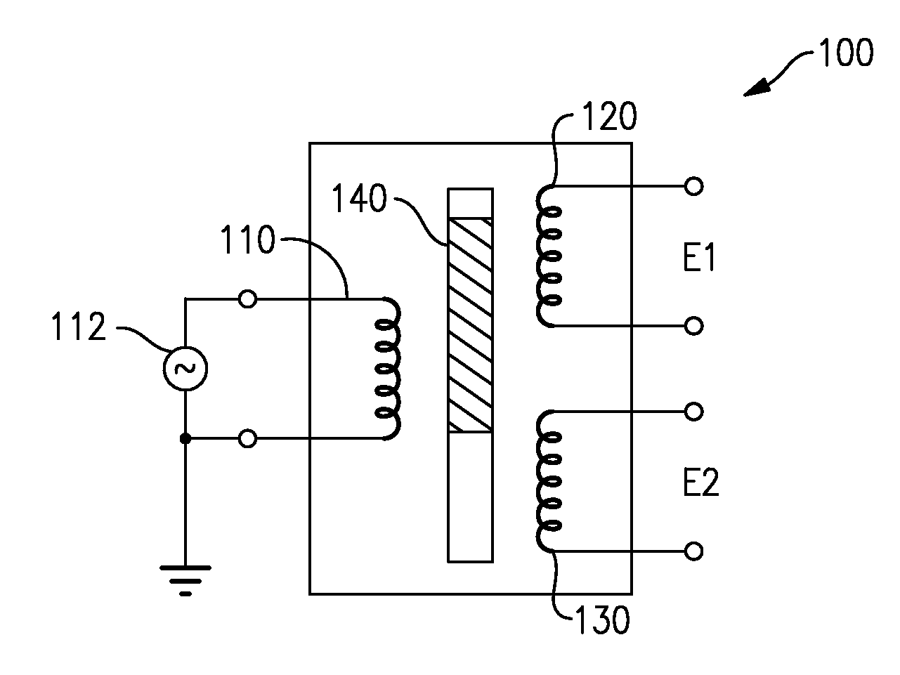
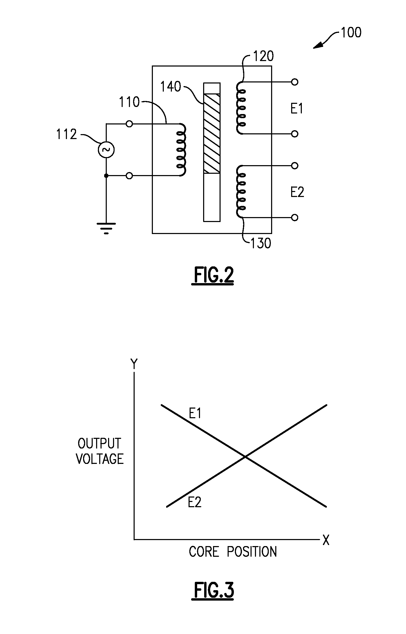
[0017]With continued reference to FIG. 1, FIG. 2 schematically illustrates an example linear variable differential transformer sensor 100 that can be used as the transformer based sensor 30. The linear variable differential transformer sen...


PUM


Abstract

A position sensor arrangement has a transformer based position sensor and a cable peaking correction apparatus. The cable peaking correction apparatus is coupled to at least one of a transformer based position sensor excitation input and the plurality of outputs from the transformer based position sensor.

Description

TECHNICAL FIELD[0001]The present disclosure relates generally to sensor arrangements utilizing differential transformers, and more particularly to a sensor arrangement including a cable peaking correction apparatus.BACKGROUND OF THE INVENTION[0002]Many aircraft systems utilize linear or rotary actuators to control the position of aircraft components. In order to provide complete control over the position of the components, a sensor is typically used to sense the position of the actuator and provide the sensed information to a signal processing device such as a controller. The controller then determines appropriate adjustments to the actuator position to affect a desired adjustment to the component position.[0003]One sensor type utilized for this type of sensing is a transformer based sensor including either shifting coils or a shifting core that shifts position along with the actuator. The shift in position of the coils or the core affects the output of the sensor in a known manner,...

Claims


Application Information

Patent Timeline
IPC IPC(8): G01B7/14G01R23/02
CPCG01R23/02G01B7/14G01D5/2046
Inventor HESS, GARY L.
Owner HAMILTON SUNDSTRAND CORP
Why Eureka
Try Eureka