Catadioptric optical system with multi-reflection element for high numerical aperture imaging

a catadioptric optical system and optical element technology, applied in the field of optical imaging, can solve the problems of limited numerical aperture, high obscuration ratio, and large total length of the optical system used in the direction of incident light, and achieve the effects of reducing the number of optical elements

Active Publication Date: 2014-08-14
CANON KK +1
View PDF6 Cites 8 Cited by
  • Summary
  • Abstract
  • Description
  • Claims
  • Application Information

AI Technical Summary

Benefits of technology

[0012]Advantageously, exemplary embodiments of the present invention address issues related to obscuration, correction of chromatic aberration and Petzval curvature, and allow for appropriate alignment without undue difficulty.

Problems solved by technology

Conventional optical systems used in these instruments often lack compactness due to the number of optical elements necessary to correct aberrations and produce good image quality.
However, as NA increases, correction of chromatic aberrations requires an ever increasing number of optical elements, which results in the total length (dimension in the direction of incident light) of the optical system being relatively larger than in the other approaches.
Although a catadioptric optical system allows for better control of aberrations and obscuration ratio, chromatic aberrations induced by individual lenses and Petzval curvature induced by multiple mirrors are appreciable and contribute significantly to quality degradation in the final image.
However, high obscuration ratios and limited numerical aperture are pervasive in these arrangements.
One of the problems encountered with the multiple reflection lens proposed by Ford is that fabrication becomes excessively costly and complicated.
Moreover, when incident light with steep incident angles is used, a large obscuration ratio and limited field of view may be observed.

Method used


Image

  • Catadioptric optical system with multi-reflection element for high numerical aperture imaging
  • Catadioptric optical system with multi-reflection element for high numerical aperture imaging
  • Catadioptric optical system with multi-reflection element for high numerical aperture imaging

Examples


numerical examples

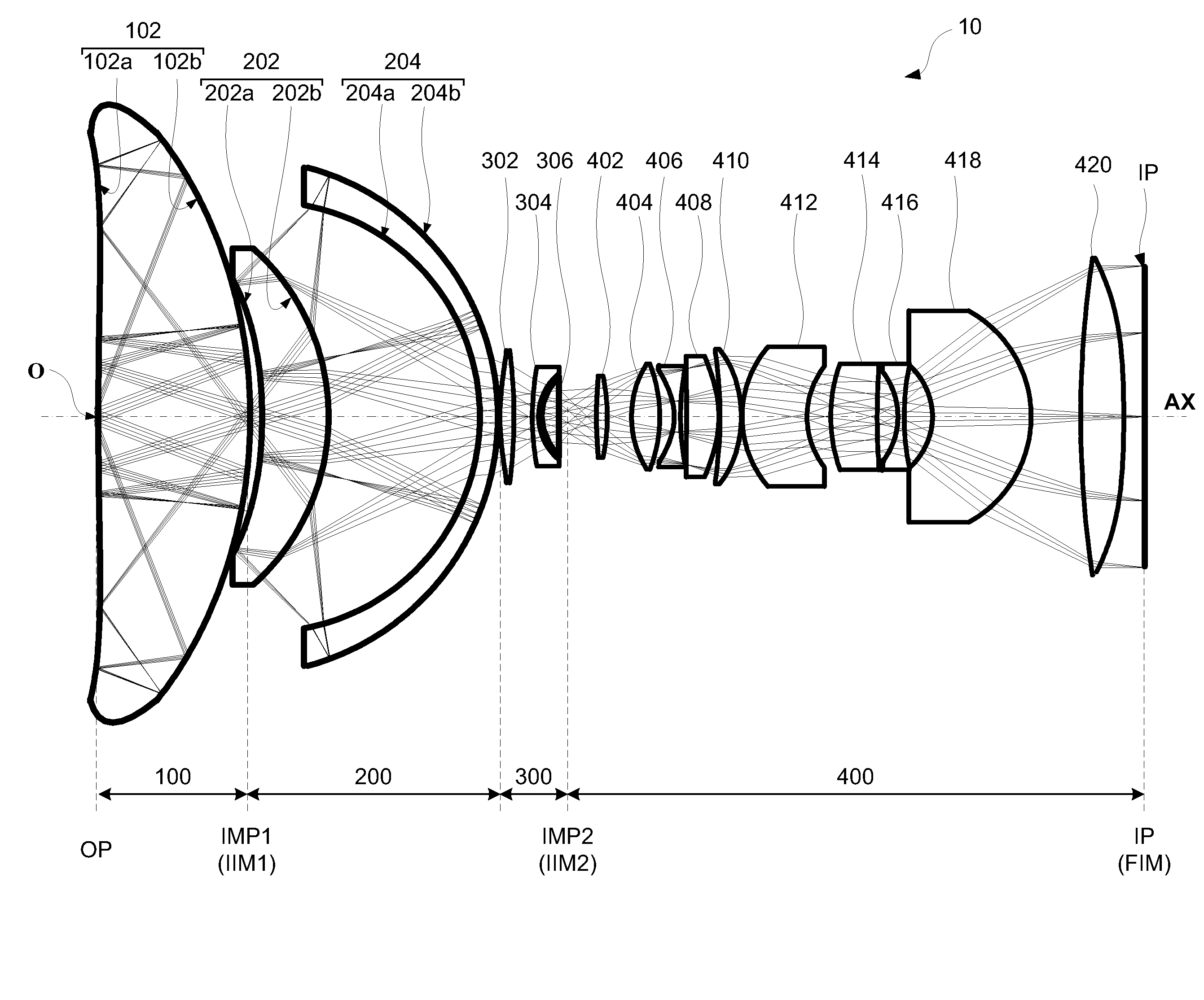
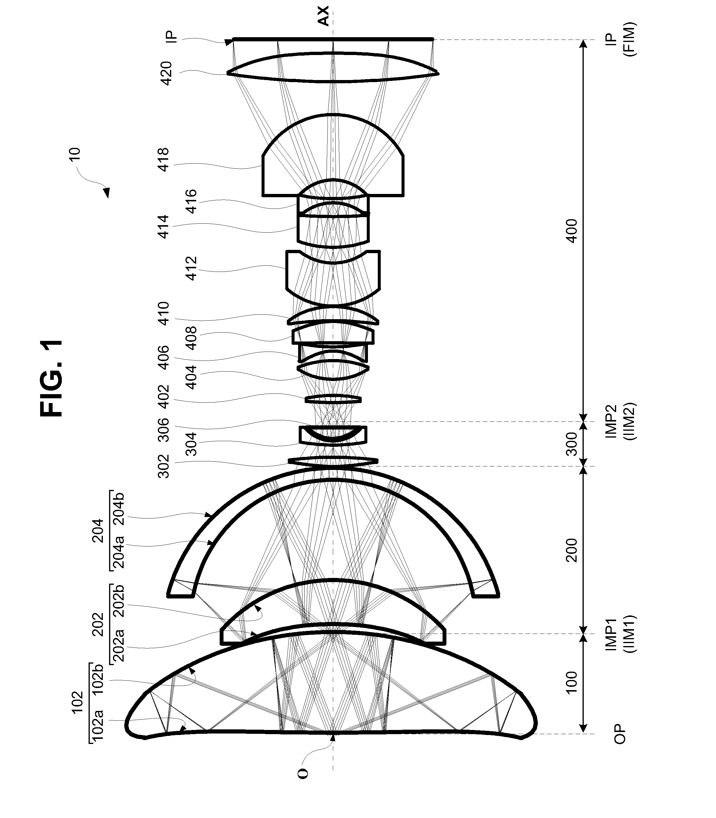
[0123]Data corresponding to the following numerical examples 1 and 2 are representative of the catadioptric optical system 10 illustrated in FIG. 1 and the catadioptric optical system 20 illustrated in FIG. 6. In the numerical examples presented herein, the reference indicia “i” (where i=1, 2, 3 . . . ) denotes the order of surfaces in the optical system from the object plane OP to the image plane IP. With this premise, the “Radius” data Ri corresponds to an ith radius of curvature (at the ith plane); thickness Ti denotes an on-axis distance (or space) between the ith and (i+1)th surface; the reference ndi and νdi respectively denote the index of refraction and Abbe number of the material of the ith optical element with respect to the Fraunhoffer d-line. A surface number without data for ndi and νdi indicates that this surface number represents an air space. A radius R=1.00E+18 (where 1E+X is equivalent to 1×10+X) denotes a substantially infinite radius, i.e., a flat surface. In add...

numerical example 1

[0125]Data corresponding to numerical example 1 represents a catadioptric optical system comprising, in order from an object side to an image side, a first catadioptric group, a second catadioptric group and a field lens group and a dioptric group disposed in axial alignment with each other, as illustrated in FIG. 1. In the catadioptric optical system of Numerical Example 1, the first catadioptric group is configured to form, at a first intermediate image plane, a first intermediate image of an object disposed at an object plane; and the second catadioptric group and the field lens group are configured to together form, at a second intermediate image plane, a second intermediate image based on the first intermediate image. A dioptric group is configured to magnify the second intermediate image and to form, at an image plane, a final image of the object based on the second intermediate image.

TABLE 3Optical element data for Numerical Example 1SurfaceRTndνd 11.00E+181.9891.77349.56 2*1...

numerical example 2

[0126]Data corresponding to numerical example 2 represents a catadioptric optical system comprising, in order from an object side to an image side, a first catadioptric group, a second catadioptric group, and a field lens group disposed in axial alignment with each other, as illustrated in FIG. 6. The first catadioptric group is configured to form, at a first intermediate image plane, a first intermediate image of an object disposed at an object plane. And the second catadioptric group and the lens group are configured to together form, at an image plane, a final image of the object based on the first intermediate image.

TABLE 5Optical element data for Numerical Example 2SurfaceRTndνd 11.00E+180.2501.77349.57 2*294.78114.9991.77349.57 3*−105.885−14.9991.77349.57 4*294.78114.9991.77349.57 5*−105.885−14.9991.77349.57 6*294.78114.9991.77349.57 7*−105.885−14.9991.77349.57 8*294.78114.9991.77349.57 9*−105.8851.5631.77349.5710*−19.50936.6081.77349.5711*−41.203−36.6081.77349.5712*−19.50936....


PUM


Abstract

A catadioptric system includes a first catadioptric group, a second catadioptric group, and a lens group disposed in axial alignment with each other. The first catadioptric group includes a solid lens having an input surface, a primary reflective surface, secondary reflective surface and an exit surface. The primary reflective surface is a curved surface concave towards the secondary reflective surface. A light flux entering through the input surface undergoes more than two reflections between the primary and secondary reflective surfaces, prior to exiting through the exit surface. At least one of the primary reflective surface and secondary reflective surface has a continuous and smooth topological profile.

Description

BACKGROUND OF THE INVENTION[0001]1. Field of the Invention[0002]The present invention is related generally to optical imaging, and more particularly it is related to a catadioptric optical system with a multi-reflection optical element for high numerical aperture imaging. The catadioptric optical system may find industrial application in microscope objective systems, lithographic projection systems or telescopic systems, among others.[0003]2. Description of the Related Art[0004]Imaging apparatuses, such as microscope objectives, lithographic projection systems, or even telescopes, use purely reflective (catoptric), purely refractive (dioptric), or a combination of reflective and refractive (catadioptric) optical elements to form an image of an object. Conventional optical systems used in these instruments often lack compactness due to the number of optical elements necessary to correct aberrations and produce good image quality.[0005]Four main design approaches have been adopted in ...

Claims


Application Information

Patent Timeline
Patent Type & Authority Applications(United States)
IPC IPC(8): G02B17/08
CPCG02B17/084G02B17/08G02B17/086G02B17/0856G02B17/0836G02B21/04
Inventor NAKANO, MASATSUGUSASIAN-ALVARADO, JOSE MANUELELAZHARY, TAMER T.
Owner CANON KK
Why Eureka
Try Eureka