Fixing device and image forming apparatus including same

a technology of fixing device and image forming apparatus, which is applied in the direction of electrographic process apparatus, instruments, optics, etc., can solve the problems of uneven temperature of fixing roller, large amount of process energy, and image quality, and achieve the effect of suppressing excess power supply, reducing uneven temperature, and improving formed image quality

Inactive Publication Date: 2014-08-14
RICOH KK
View PDF3 Cites 20 Cited by
  • Summary
  • Abstract
  • Description
  • Claims
  • Application Information

AI Technical Summary

Benefits of technology

[0014]The present invention aims to suppress uneven temperature on the surface of the fixing member so that the formed image quality is improved, thereby suppressing an excess power supply and reducing power consumption.
[0015]The present invention provides an improved fixing device that includes a rotatable fixing member to rotate while contacting an unfixed image on a sheet of recording medium; a pressure member to form a fixing nip portion with the fixing member; a heating member divided into a plurality of individual heating elements in a direction perpendicular to a conveyance direction of a sheet of recording medium; a heat performance sensor to detect heating performance of each heating element of the heating member, and an controller to control the heating member. Image fixing is performed by passing the sheet of recording medium carrying an unfixed image thereon through the nip portion. The controller controls each heating element independently such that a temperature of a portion of the fixing member corresponding to a blank area on the recording medium becomes lower than the temperature of a portion of the fixing member corresponding to an image area. The external heater further controls the temperature to be maintained at each heating element based on the detection result of the heating performance of each heating element detected by the heat sensor.

Problems solved by technology

As a result, it takes several minutes for the fixing roller to reach a target temperature suitable for fixing the toner image on the recording medium.
Therefore, this type of fixing roller must maintain a certain temperature even during standby when image formation is not performed, consuming a large amount of energy in the process.
In this case, each heating element may include variations in the heating due to initial or cumulative changes derived from manufacturing errors that in turn may produce high electrical density area and low electrical density areas.
Further, variations in the temperature of the belt that contacts the unfixed or blank image degrade image quality and cause defective image formation.

Method used


Image

  • Fixing device and image forming apparatus including same
  • Fixing device and image forming apparatus including same
  • Fixing device and image forming apparatus including same

Examples


first embodiment

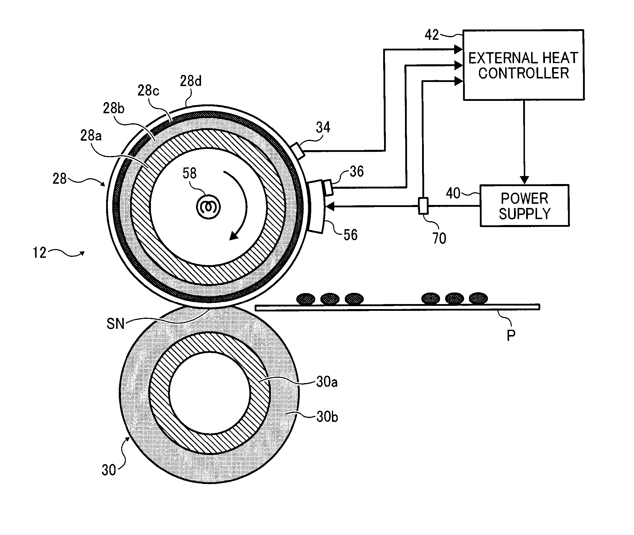
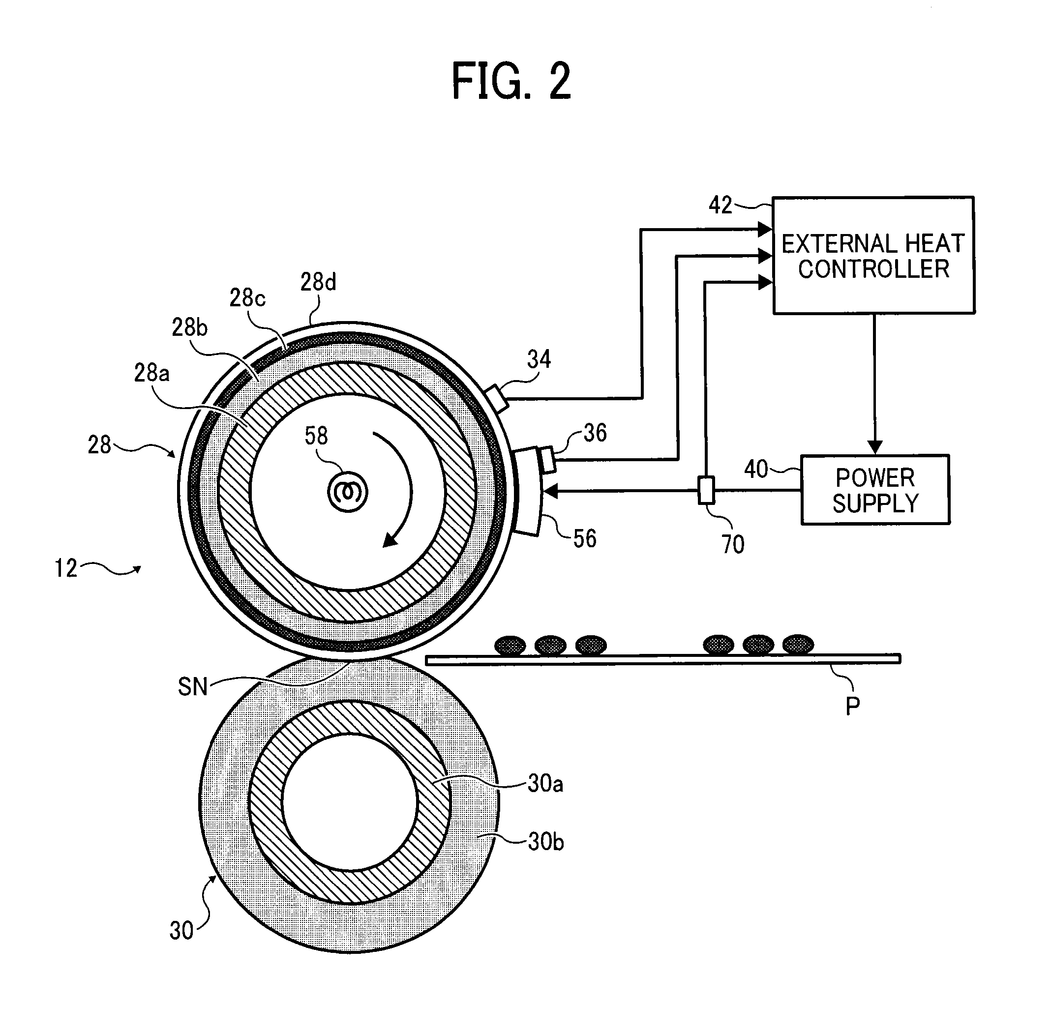
[0036]As illustrated in FIGS. 2 and 3, the fixing device 12 employs an external heating method. That is, the fixing device 12 is constructed of a fixing roller 28, a pressure roller 30, a thermal heater 56, a heat sensor 70, and the like. The fixing roller 28 rotatably contacts an unfixed-image to serve as a fixing member. The pressure roller 30 presses against the fixing roller 28 and forms a fixing nip portion SN along with the fixing roller 28. The thermal heater 56, located outside the fixing roller 28 and supplied with power from a commercial power supply 40, heats the fixing roller. The heat sensor 70 detects heating of each heating element of the thermal heater 56. The thermal heater 56 and the power supply 40 construct an external heater means.

[0037]The thermal heater 56 is constructed of multiple heating elements 56a, 56b, 56c, 56d, 56e, 56f, and 56g, which are disposed at equal intervals in the width direction of the sheet P. Each heating element 56a, 56b, 56c, 56d, 56e, ...

second embodiment

[0065]Next, as described referring to FIGS. 6 and 7, the fixing device 12 according to the present invention will be described.

[0066]FIG. 6 is a schematic cross-sectional view of the fixing device 12 according to the second embodiment of the present invention. The fixing device 12 according to the second embodiment includes a thermal or ceramic heater 56. The heater 56 is constructed of a planar base and heating elements formed on the planar base. The thermal heater 56 is disposed inside a belt or film and provides heat to the belt or film to increase temperature, so that the unfixed image conveyed to the fixing nip portion SN is heated and fixed.

[0067]The thermal heater 56 is disposed upstream of the fixing nip portion SN because a certain length of time is required for the heat from the thermal heater 56 disposed inside the belt or film to reach a surface of the fixing roller 28. Alternatively, the thermal heater 56 may be disposed in the vicinity of the fixing nip portion SN. Thi...

fourth embodiment

[0074]FIG. 9 illustrates a fixing device 12 according to the present invention.

[0075]As illustrated in FIG. 9, the fixing device 12 includes a fixing belt 38 as a fixing rotary member, a pressure roller 30 as an opposite member configured to contact the fixing belt 38 and form a nip portion SN, and a heater 56 configured to heat the fixing belt 38. A contact surface between the heater 56 and the fixing belt 38 is a substantially flat plane.

[0076]The fixing belt 38 is formed of a thin, flexible endless belt. Specifically, the fixing belt 38 is constructed of a base member 38a formed of a stainless steel (SUS) having an external diameter of 40 mm and a thickness of 40 μm, an elastic layer 38b coated to have a thickness of 100 μm on a circumferential surface of the base member 38a, and a release layer 38c formed of fluorine resins such as tetrafluoroethylene-perfluoroalkyl vinylether copolymer (PFA) or polytetrafluoroethylene (PTFE) coated to have a thickness of from 5 μm to 50 μm on a...


PUM


Abstract

A fixing device includes a rotatable fixing member to rotate while contacting an unfixed image; a pressure member to form a fixing nip with the fixing member; a heating member having a plurality of heating elements divided in a direction perpendicular to a conveyance direction of a sheet; a heat performance sensor to detect heating performance of each heating element of the heating member, and an controller to control the heating member. The controller controls each heating element independently such that a temperature of a portion of the fixing member corresponding to a blank area becomes lower than the temperature of a portion of the fixing member corresponding to an image area; and controls the temperature to be maintained at each heating element based on the detection result of the heating performance of each heating element detected by the heat performance sensor.

Description

CROSS-REFERENCE TO RELATED APPLICATIONS[0001]The present application claims priority pursuant to 35 U.S.C. §119 from Japanese patent application numbers 2013-026534, and 2013-263684, filed on Feb. 14, 2013, and Dec. 20, 2013, respectively, the entire disclosures of which are incorporated by reference herein.BACKGROUND[0002]1. Technical Field[0003]The present invention relates to a thermally heated fixing device for use in an image forming apparatus employing electrophotography, and to an image forming apparatus such as a printer, a facsimile machine, a copier, and the like, including such a fixing device.[0004]2. Related Art[0005]In image forming apparatuses such as copiers, printers, and facsimile machines, a toner image is formed on an image carrier based on image data, the thus-formed toner image is transferred on a recording medium such as a sheet of paper or OHP film, and the recording medium carrying the toner image thereon is treated by a fixing device that fixes the toner im...

Claims


Application Information

Patent Timeline
Patent Type & Authority Applications(United States)
IPC IPC(8): G03G15/20
CPCG03G15/205G03G15/2042
Inventor KISHI, KAZUHITOWAIDA, TAKUMISAMEI, MASAHIROONO, HIROSHIYAMAMOTO, TAKESHIFUJIMOTO, IPPEISEO, HIROSHIYAMASHINA, RYOTAISHIGAYA, YASUNORIFUJITA, TAKASHI
Owner RICOH KK
Why Eureka
Try Eureka