
Electrical Connector

a technology of electrical connectors and connectors, applied in the direction of coupling contact members, coupling device connections, electric discharge lamps, etc., to achieve the effect of increasing the speed of signal transmission

Active Publication Date: 2014-08-14
3M INNOVATIVE PROPERTIES CO
View PDF15 Cites 34 Cited by
  • Summary
  • Abstract
  • Description
  • Claims
  • Application Information

AI Technical Summary

Benefits of technology

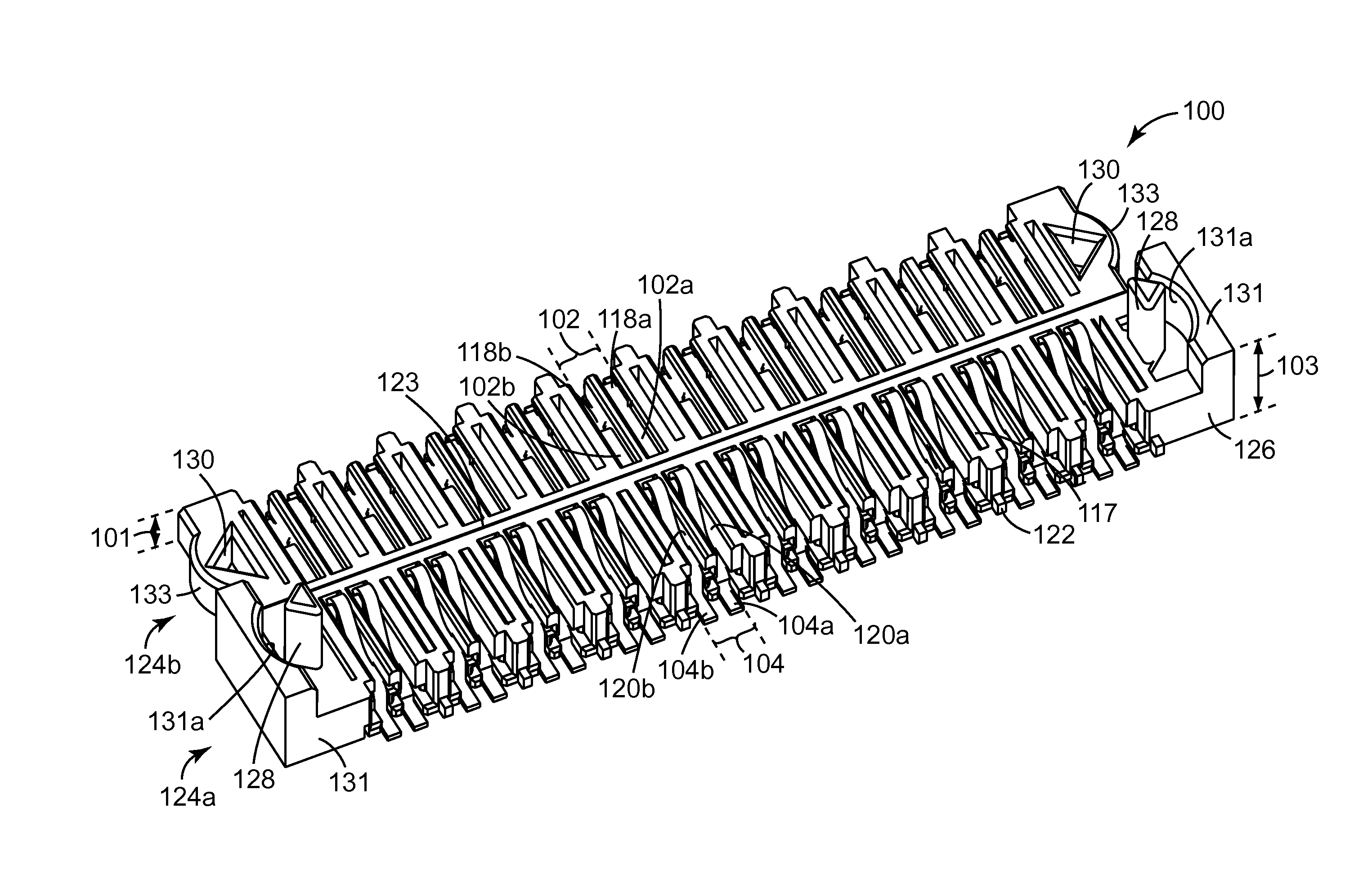
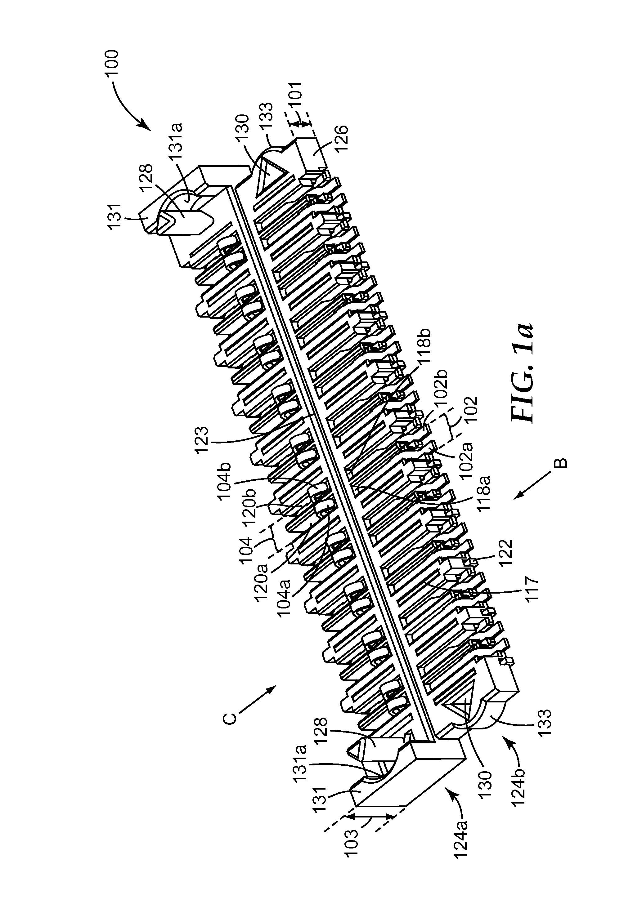
The described embodiment of the patent allows for flexibility in arranging terminals, which results in a smaller electrical connector. The terminals have different profiles, lengths, and electrical lengths which help to overcome timing offsets when mated with another electrical connector. The low stack height of the connector increases the speed of signal transmission and allows for space-constrained drives to be overcome.

Problems solved by technology

It is a challenge to improve on the performance of electrical connectors and electrical connector assemblies while providing electrical connectors of sizes which meet certain technical requirements.

Method used


Image

  • Electrical Connector
  • Electrical Connector
  • Electrical Connector

Examples


embodiment 1

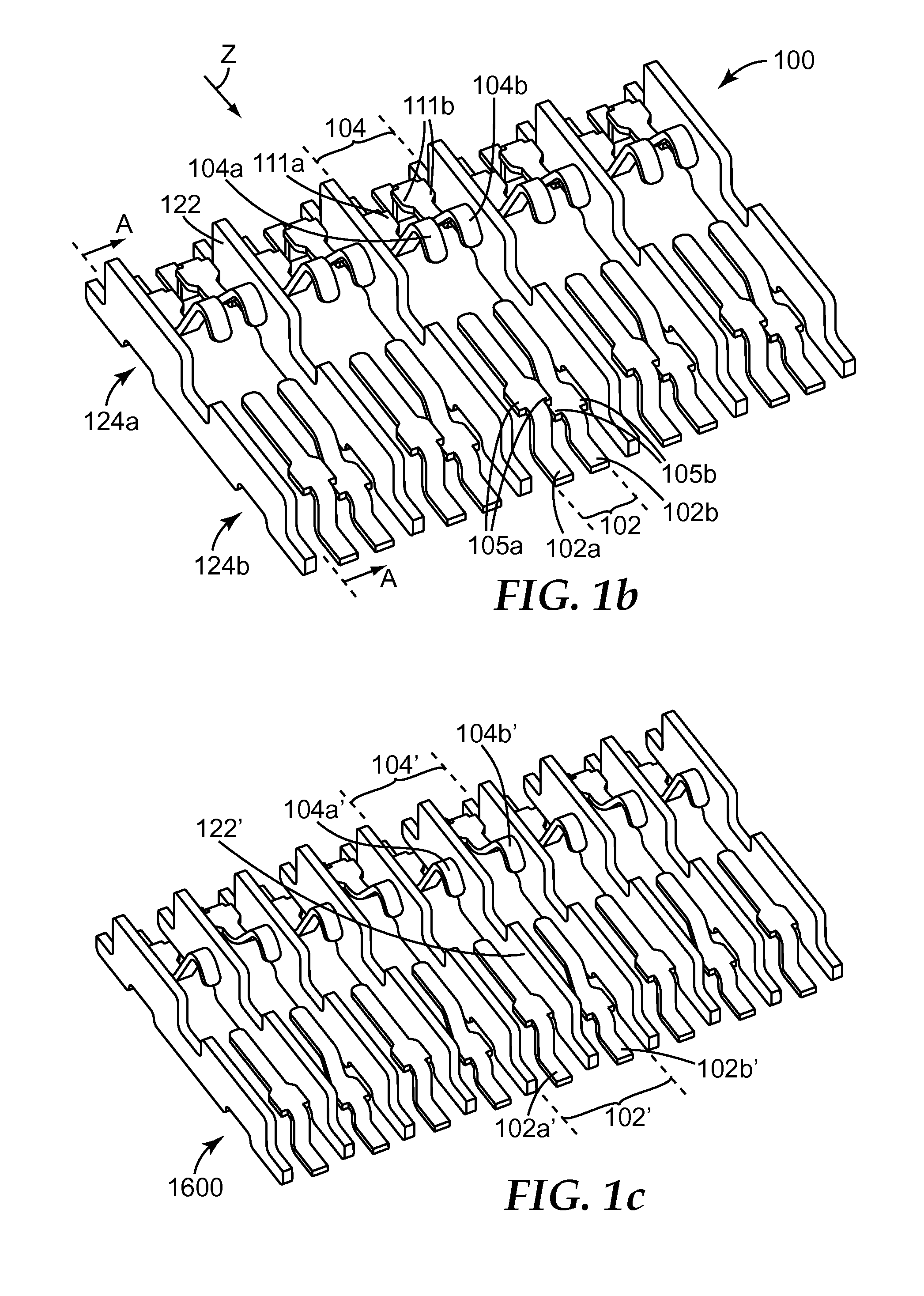
[0111 is an electrical connector comprising first and second terminal pairs configured to electrically couple to a same device, each terminal pair comprising terminals, with the terminals in the first terminal pair having different first and second electrical lengths and the terminals in the second terminal pair having different third and fourth electrical lengths, wherein a sum of the first and third electrical lengths is substantially the same as a sum of the second and fourth electrical lengths.

embodiment 2

[0112 is an electrical connector according to embodiment 1, wherein the terminals in at least one of the first and second terminal pairs have different longitudinal profiles.

embodiment 3

[0113 is an electrical connector according to embodiment 1 or 2, wherein at least one terminal in the first pair of terminals has a different longitudinal profile than at least one terminal in the second pair of terminals.


PUM


Abstract

An electrical connector (100) is disclosed. In a described embodiment, the electrical connector (100) comprises first and second terminal pairs (102, 104) configured to electrically couple to a same device, each terminal pair (102, 104) comprising terminals (102a, 102b, 104a, 104b), with the terminals (102a, 102b) in the first terminal pair (102) having different first and second electrical lengths and the terminals (104a, 104b) in the second terminal pair (104) having different third and fourth electrical lengths, wherein a sum of the first and third electrical lengths is substantially the same as a sum of the second and fourth electrical lengths.

Description

FIELD OF THE INVENTION[0001]This invention relates to an electrical connector, particularly but not exclusively to a board-to-board connector.BACKGROUND OF THE INVENTION[0002]Conventional board-to-board electrical connectors and electrical connector assemblies are generally used in low-speed transmission applications whereby the amounts of cross talk (both near end and far end) and electromagnetic interference (EMI) are not critical.[0003]However, in recent years, there has been a significant increase in the required data rate (in turn, the required rise time of signals) for several applications. In order to meet this increasing need for high-speed transmission, it is preferable to design electrical connectors and electrical connector assemblies such that these connectors and connector assemblies have superior performance over frequencies in the GHz range. Further, in line with an increasing demand for smaller and more compact devices, sizes of electrical connectors also have to be ...

Claims


Application Information

Patent Timeline
IPC IPC(8): H01R13/6473
CPCH01R13/6473H01R12/71H01R24/84H01R13/28H01R12/716
Inventor LIM, CHIN HUABANDHU, SAUJIT
Owner 3M INNOVATIVE PROPERTIES CO
Learn More