Microelectromechanical device with signal routing through a protective cap

a micro-electromechanical device and protective cap technology, applied in microstructural technology, acceleration measurement using gyroscopes, speed measurement using gyroscopic effects, etc., can solve the problem of limiting the communication between the sensors integrated in the die and the external environment, the area used by the pads and the corresponding connection lines cannot be reduced beyond a certain limit, etc. problem, to achieve the effect of low yield per unit area and high device cos

Active Publication Date: 2014-08-21
STMICROELECTRONICS SRL
View PDF3 Cites 4 Cited by
  • Summary
  • Abstract
  • Description
  • Claims
  • Application Information

AI Technical Summary

Benefits of technology

[0008]In addition to the technical difficulties to be tackled for design of the connections, the yield per unit area is low, and the cost of the device is high.

Problems solved by technology

The trend towards miniaturization and to integration has encountered, however, a limit in the need to enable communication of the sensors integrated in the die with the external environment, in particular with the control devices that are typically obtained in separate dice.
Paradoxically, whilst sophisticated solutions from the mechanical and electrical standpoint enable design of extremely compact microstructures, the area used by the pads and by the corresponding connection lines cannot be reduced beyond a certain limit.
Integrated sensors capable of detecting several independent quantities hence use a considerable expenditure in terms of area.
In addition to the technical difficulties to be tackled for design of the connections, the yield per unit area is low, and the cost of the device is high.

Method used


Image

  • Microelectromechanical device with signal routing through a protective cap
  • Microelectromechanical device with signal routing through a protective cap
  • Microelectromechanical device with signal routing through a protective cap

Examples


Embodiment Construction

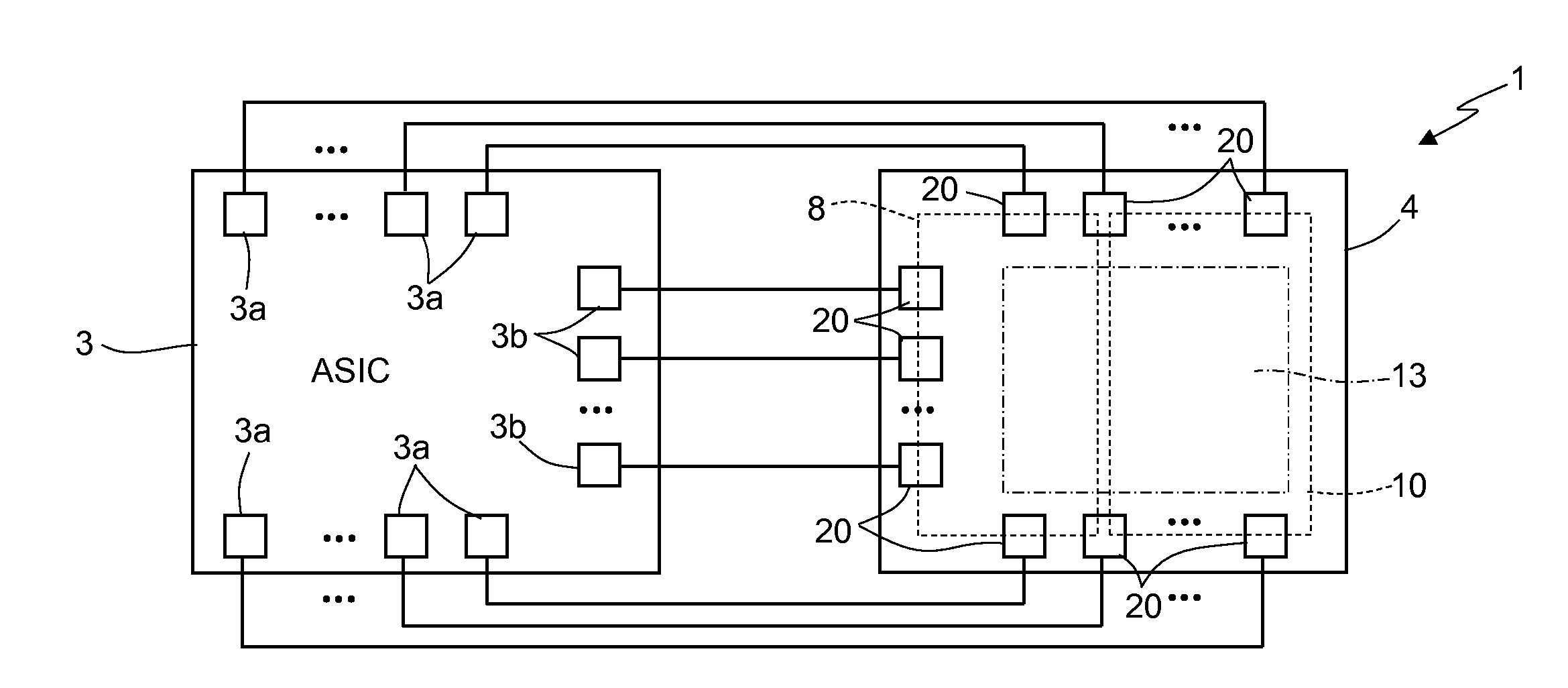
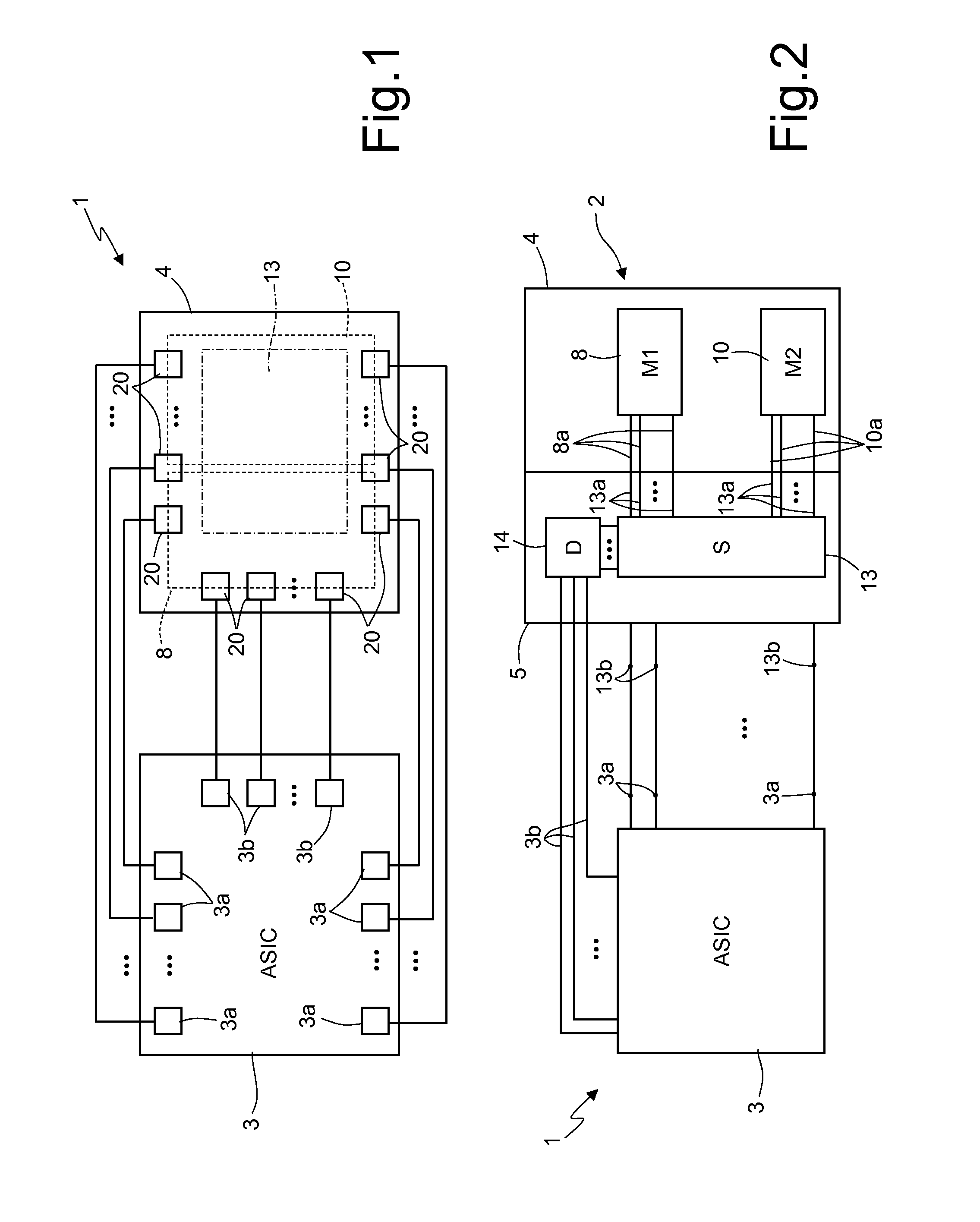
[0025]With reference to FIGS. 1 and 2, a multiaxial microelectromechanical sensor is illustrated schematically and is designated as a whole by 1. The microelectromechanical sensor 1 comprises a structural component 2 and a control circuit or ASIC (Application-Specific Integrated Circuit) 3.

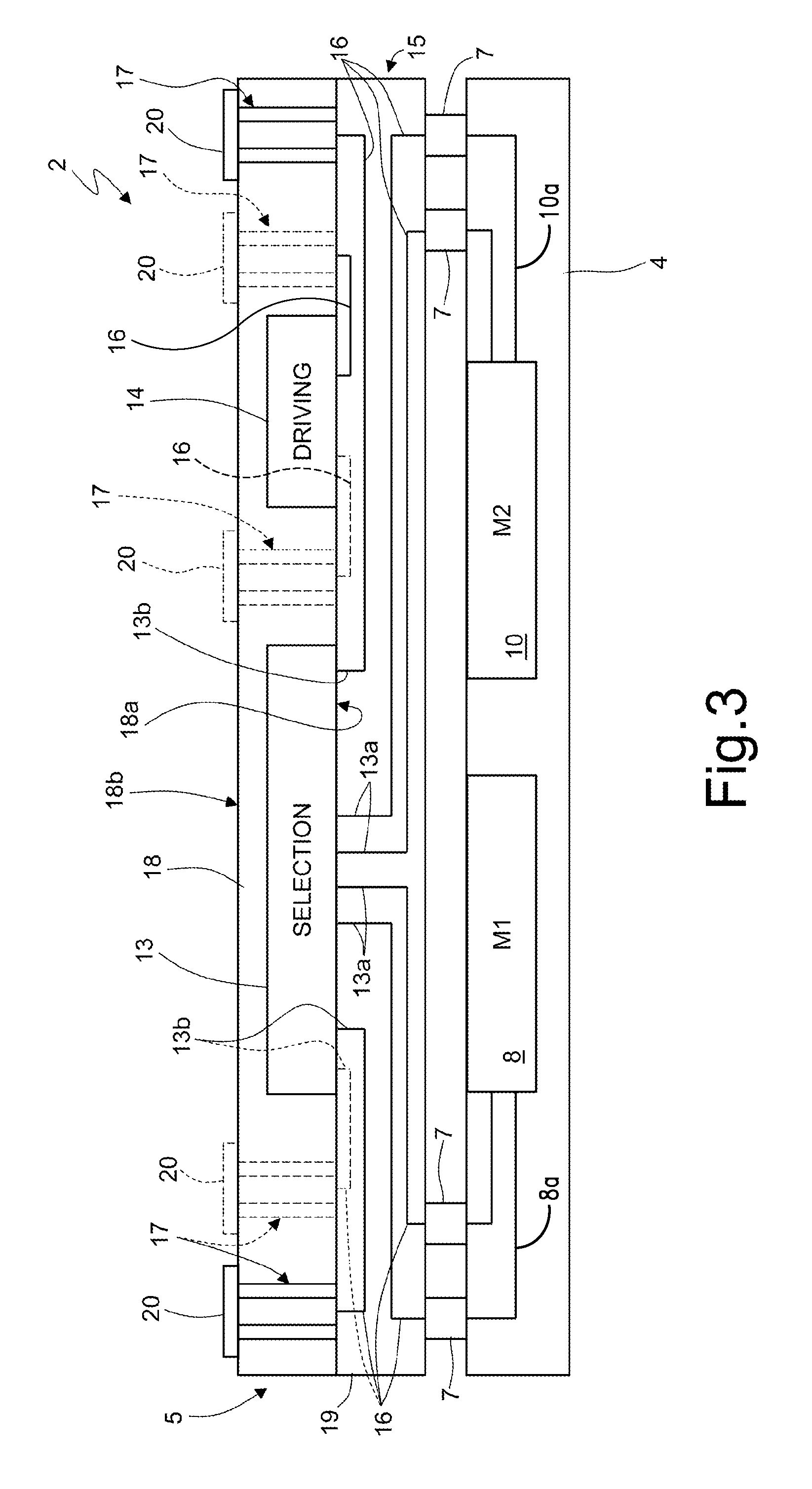
[0026]The structural component 2 in turn comprises a microstructure chip 4 and a protective cap 5, bonded to one another through conductive bonding regions 7, see FIG. 3.

[0027]According to an embodiment, the microstructure chip 4 accommodates a first microelectromechanical structure 8 and a second microelectromechanical structure 10, which form structural parts, respectively, of a multiaxial accelerometer and of a multiaxial gyroscope of a capacitive type. In what follows, these microelectromechanical structures will be referred to, for simplicity, as “microstructure 8” and “microstructure 10”.

[0028]The first microstructure 8 and the second microstructure 10 have respective sets of terminals 8a, 1...


PUM


Abstract

A microelectromechanical device includes: a body accommodating a microelectromechanical structure; and a cap bonded to the body and electrically coupled to the microelectromechanical structure through conductive bonding regions. The cap including a selection module, which has first selection terminals coupled to the microelectromechanical structure, second selection terminals, and at least one control terminal, and which can be controlled through the control terminal to couple the second selection terminals to respective first selection terminals according, selectively, to one of a plurality of coupling configurations corresponding to respective operating conditions.

Description

BACKGROUND[0001]1. Technical Field[0002]The present disclosure relates to a microelectromechanical device with signal routing through a protective cap and to a method of controlling the microelectromechanical device.[0003]2. Description of the Related Art[0004]As is known, the use of microelectromechanical systems (MEMS) has encountered an ever-increasing spread in various sectors of technology and has yielded encouraging results especially in the production of inertial sensors, microintegrated gyroscopes, and electromechanical oscillators for a wide range of applications.[0005]Under the thrust of the increasing request for high performance and flexibility of use, the technology has rapidly developed and has led to the production of miniaturized microelectromechanical sensors capable of detecting different independent quantities. For example, numerous solutions have been proposed regarding multiaxial movement sensors (accelerometers and gyroscopes) using microstructures integrated i...

Claims


Application Information

Patent Timeline
Patent Type & Authority Applications(United States)
IPC IPC(8): B81B7/00
CPCB81B7/008B81B2201/0242B81B2201/0235B81B7/007B81B7/0074B81B7/02B81C1/0023B81C2203/0792B81C2203/0118B81B2207/012B81B2207/092B81B2207/07B81B2207/015B81B2207/096B81B2207/097B81B2207/093H01L2924/0002H01L2924/00H01L2224/18
Inventor ALLEGATO, GIORGIOSIMONI, BARBARAVALZASINA, CARLOCORSO, LORENZO
Owner STMICROELECTRONICS SRL
Why Eureka
Try Eureka