Laser decontamination device

a laser and decontamination technology, applied in radioactive decontamination, nuclear engineering, manufacturing tools, etc., can solve the problems of grinding devices such as the nozzle of sandblasts, unable to remove ris advanced deep into the microscopic cracks on the metallic surface at all, and the power density to be lowered, so as to achieve accurate measurement, time and labor-saving decontamination, the effect of further enhancing the scanning velocity of the laser beam

Active Publication Date: 2014-09-18
MINEHARA EISUKE
View PDF21 Cites 28 Cited by
  • Summary
  • Abstract
  • Description
  • Claims
  • Application Information

AI Technical Summary

Benefits of technology

[0025]The invention brings the following favorable effects.
[0026]According to the present invention, making the laser beam converged onto minute regions on the surface of the contaminated article by means of the imaging optical system (Z axis scanner) and the focal length of the laser beam precisely adjustable in accordance with the surface of the contaminated article by means of the Z axis scanner permits the power density of the laser beam to be increased up to in the order of GW / cm2 that is larger almost by three orders of magnitudes than the conventional counterpart, so that inclusively the RIs advanced deeply into the contaminated article can be completely spalled, evaporated and sublimated along with the base material.
[0027]Further, according to the present invention, the condensing optic system is disposed nearer to the light source than the XY axis scanner such that the measuring laser beam emitted from the laser range finder does not pass through such system, with the result that the surface shape of the target can be accurately measured. Likewise, not using the numeral pieces of compound lenses permits a laser beam of high output power to be irradiated onto the object contaminated with the RIs with such beam hardly attenuated or without the apprehension that the lenses comprising such system might be broken.
[0028]Moreover, according to the present invention, based on the data (cubic map) of the surface shape of the contaminated article measured by the surface shape measuring device, the focus position controlling section of the Z axis scanner automatically adjusts the focus of the laser beam according to an irradiation position, so that time and labor-saving decontamination can be performed without uneven irradiation density even when the surface of the contaminated article can be irregular.
[0029]Further, arranging the scanning device with the XY axis scanner employing the beam reflectors (such as galvano-mirrors) and the Z axis scanner employing the movable lens (or a variable focus lens) as described in the present invention allows the scanning velocity of the laser beam to be further enhanced than when the surface of the contaminated article is scanned with the laser head moved, which enables non-thermal machining to be performed even with the laser beam whose power density is higher, with the result that the thermally induced diffusion and reattachment of the RIs can be prevented.
[0030]Furthermore, with the CW laser that continuously emits laser beams L1 used for the laser oscillator 1, the focused beam size can be rendered pretty smaller than that of the pulse laser so that not only irradiation density can be set higher, but also it allows the three-dimensional scanning to be performed with precision in accordance with the surface shape of the contaminated article. Also in the aspect of the related cost, it can be saved further than the pulse laser, the cost of which device per laser unit output is higher and the efficiency of which conversion from electricity to beam is lower.

Problems solved by technology

However, according to the above method by which the pulse laser beams are rendered into parallel light, making the condensed area smaller for the purpose of enhancing the power density (irradiation intensity) unavoidably leads to causing uneven irradiation, so that the same spot shall be irradiated several times. On the other hand, enlarging an irradiation area of one pulse causes the power density to be lowered (in the order of some MW / cm2 or less) so that the irradiated beams result in being reflected from the lustrous metallic surface, with the result that the RIs advanced deeply into the microscopic cracks on the metallic surface cannot be removed at all.
However, according to the above-mentioned mechanical methods, during the grinding not only the RIs are ready to reenter the surface so as to cause recontamination, but also the grinding device (such as the nozzle of the sandblast) is secondarily contaminated by the grinding particles of the sandblast, the grinding belt of the sander or grinder or the grinding disk that are used repeatedly.
Further, providing that the sandblasts and sanders secondarily contaminated by the grinding particles or belt are exchanged with new ones every time the decontaminations are carried out, it makes the cost incurred for exchanging such mechanical devices and their parts so bulky that not only the decontamination cost goes overboard, but also a large volume of secondary wastes are produced, which is unfavorable in view of the cost-saving aspect and the eco-friendly trend.
Moreover, uneven irradiation density might happen on the surface of the object with irregularities.
Furthermore, where such high-output pulsed laser beams are employed, it requires that the thermally induced diffusion and reattachment of the RIs be taken into due account, besides, with the method by which the laser beams are irradiated with the laser head moved, because there is limit in the scanning velocity for the low-velocity motion even when it might be automatically scanned, the thermally induced diffusion of the RIs is aggravated in which the portions onto which the beams are irradiated result in being extensively and deeply fused and thermally affected.
On the other hand, a laser machining device in which a focal length is adjusted with a beam expander in use is also well known (refer to Patent Literature 2), but with such device, the condensing optical system including compound lenses are disposed posterior to the XY scanner, so that it often happens that measuring a surface shape with a laser range finder fails because the reflected light from the object is under the influences of such compound lenses and as such.
Further, passing the machining and measuring laser beam through the compound lenses and as such makes such beam greatly attenuated, so that the available machining laser beam unavoidably results in being smaller in output power.

Method used


Image

  • Laser decontamination device
  • Laser decontamination device
  • Laser decontamination device

Examples


first embodiment

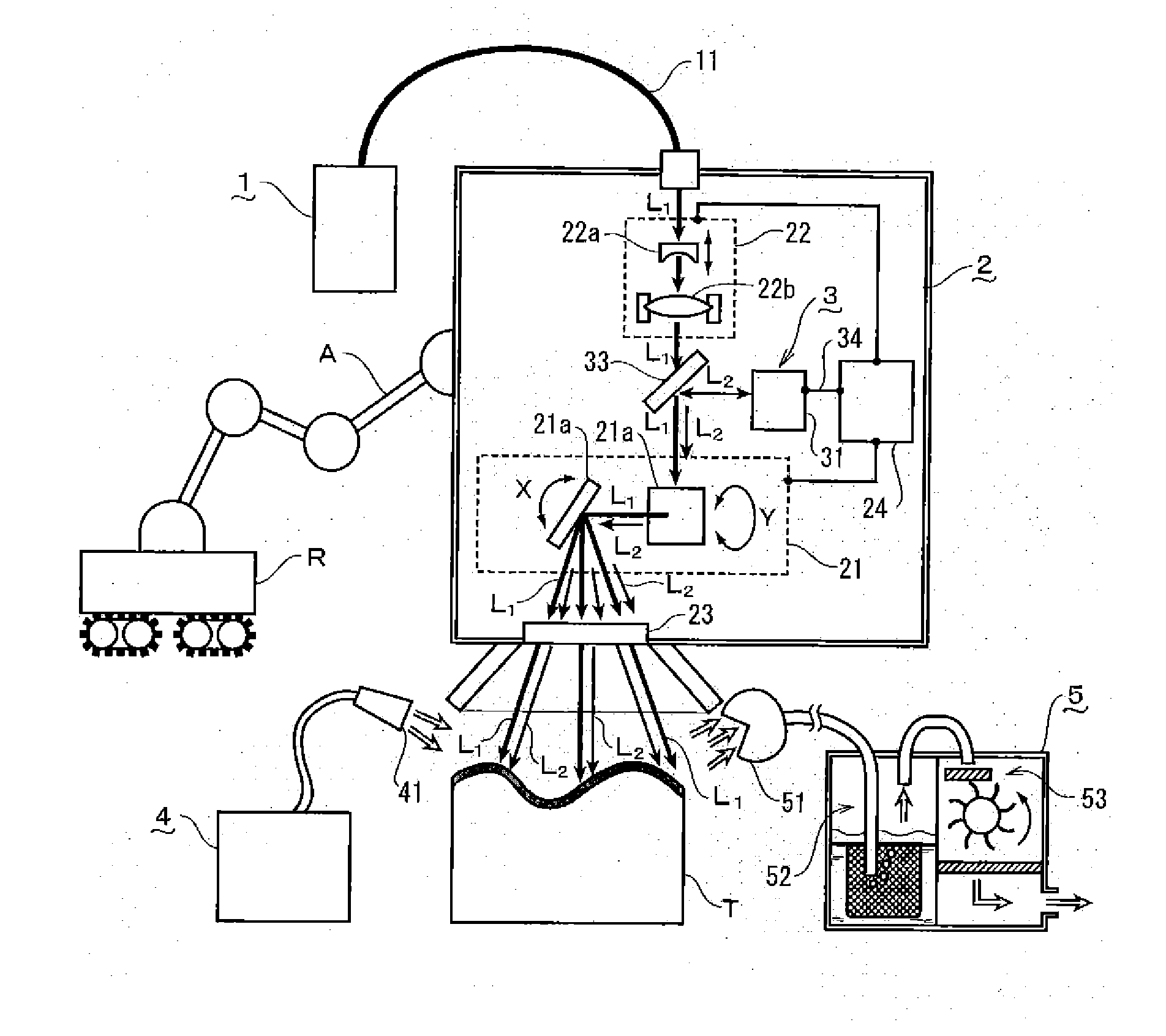
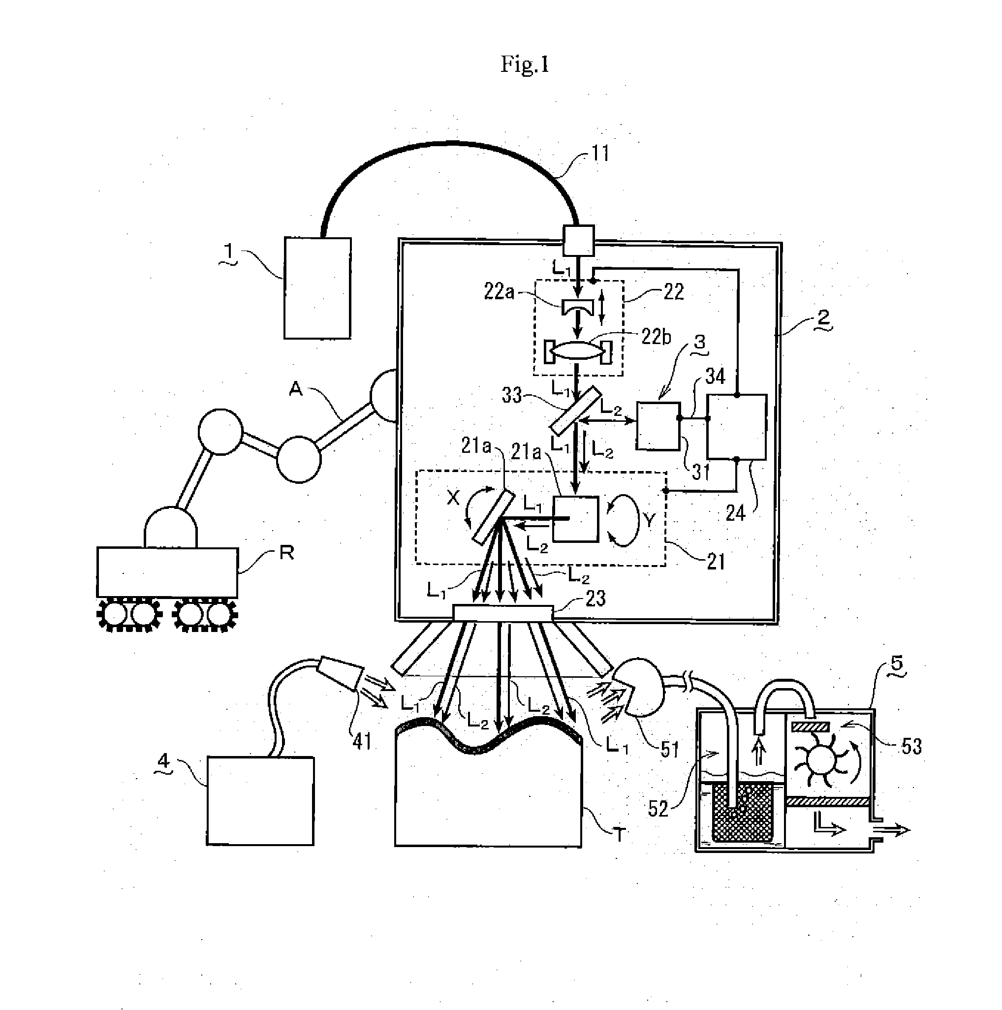
[0038]The first embodiment of the invention is explained with reference to FIGS. 1 to 4, in which the laser oscillator 1, the scanning device 2, the surface shape measuring device 3, the gas jet-spraying device 4 and the removals collecting device 5 are illustrated.

(Arrangement of the Laser Decontamination Device)

[0039]According to the first embodiment, the laser oscillator 1 that is the light source of a machining laser beam L1 is connected through a long optical fiber 11 to the scanning device 2 that condenses the laser beam L1 onto the surface of a contaminated article T for scanning. To note, the fiber laser provided with the optical fiber 11 smaller in diameter is used for the laser oscillator 1.

[0040]Further, in the present embodiment, in order to further enhance the power density of the laser beam L1, not the pulse laser, but the CW laser by which a focused beam size can be minimized is adopted for the laser oscillator 1. Further, the CW laser costs lower than the pulse laser...


PUM

PropertyMeasurementUnit
diameteraaaaaaaaaa
scanning velocityaaaaaaaaaa
thicknessaaaaaaaaaa

Abstract

The laser decontamination device includes: a laser oscillator; a scanning device provided with an XY axis scanner and a Z axis scanner to condense the laser beam emitted from the laser oscillator onto the surface of the contaminated article without the intervention of any compound lens such as an f θ lens so as to optically scan the surface; and a surface shape measuring device to measure the surface shape of the contaminated article, the Z axis scanner being provided with a focus position controlling section to automatically adjust a focus position in accordance with an irradiation position such that a focus of the laser beam comes on the surface of the contaminated article based on a shape data obtained at the surface shape measuring device.

Description

TECHNICAL FIELD[0001]The present invention relates to an improvement on a laser decontamination device, in details, pertaining to such device allowing the containers and equipment contaminated by RI (Radioisotopes) in nuclear power plants under recovery owing to the nuclear accidents or under decommissioning, facilities in which such RIs are stored, nuclear reprocessing factories, nuclear fuel storage facilities, accelerator facilities and so forth to be decontaminated with efficiency and decontamination performance to be further enhanced than the conventional counterpart.BACKGROUND ART[0002]Conventionally, such decontamination method by laser is known as irradiating substantially parallel light pulse laser beams of lower average power output onto the surface of the objects contaminated by the RIs with such objects linearly or planarly scanned, the device employing which method is characterized in that the contaminants deriving from RIs, which are black and others in color and highe...

Claims


Application Information

Patent Timeline
Patent Type & Authority Applications(United States)
IPC IPC(8): B23K26/00B23K26/03B23K26/04B23K26/08B23K26/14B23K26/142B23K26/36G21F9/28
CPCB23K26/0066B23K26/36G21F9/28G21F9/005G21F9/30B23K26/142B23K26/082B23K26/08
Inventor MINEHARA, EISUKE
Owner MINEHARA EISUKE
Why Eureka
Try Eureka