Plastic stand and method of attachment to a pressure vessel

Active Publication Date: 2014-08-21
AMTROL LICENSING INC
View PDF66 Cites 9 Cited by
  • Summary
  • Abstract
  • Description
  • Claims
  • Application Information

AI Technical Summary

Benefits of technology

[0008]In certain embodiments, the upper wall of the stand further includes a plurality of drainage apertures defined therethrough. The drainage apertures are configured and adapted to permit airflow and drainage through the upper wall of the stand. At least one access aperture can be defined in the sidewall of the stand, to permit a fluid conduit to pass therethrough. The stand can include a lower wall extending outward from a lower end of the sidewall, to present a flat contact surface with the ground to prevent sinking of

Problems solved by technology

However, due to exposure to weather, standing water and other elements, corrosion

Method used


Image

  • Plastic stand and method of attachment to a pressure vessel
  • Plastic stand and method of attachment to a pressure vessel
  • Plastic stand and method of attachment to a pressure vessel

Examples


Example

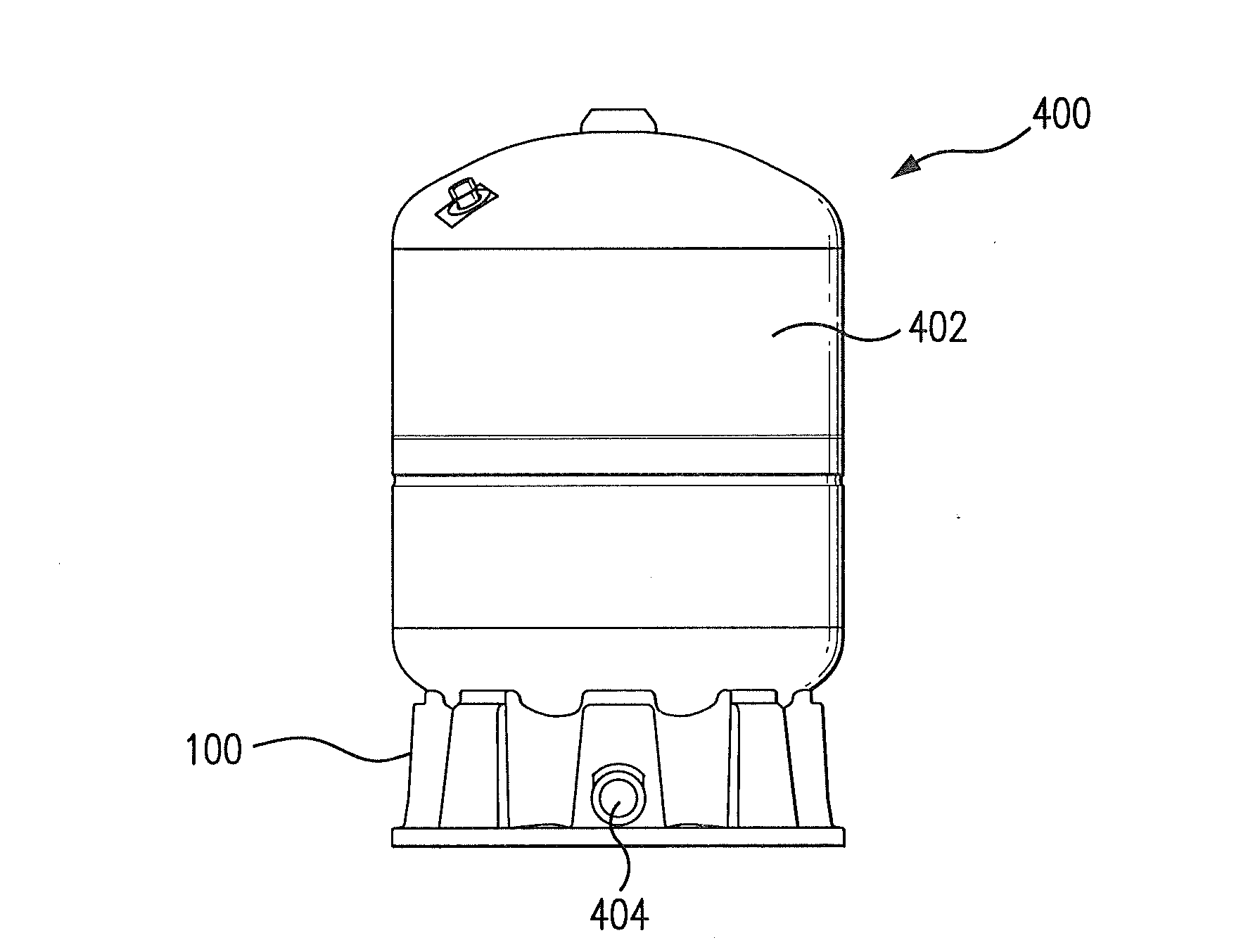
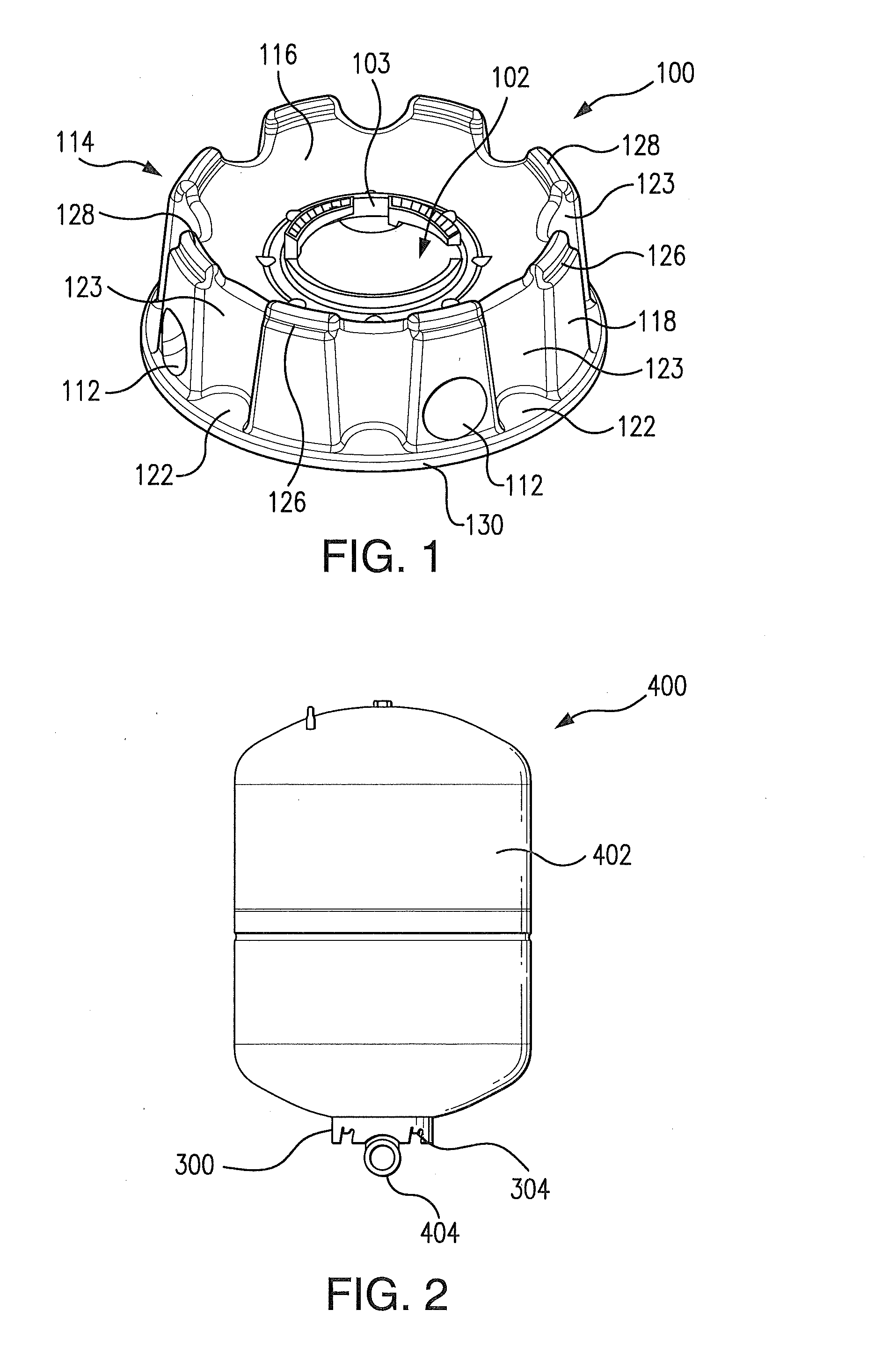
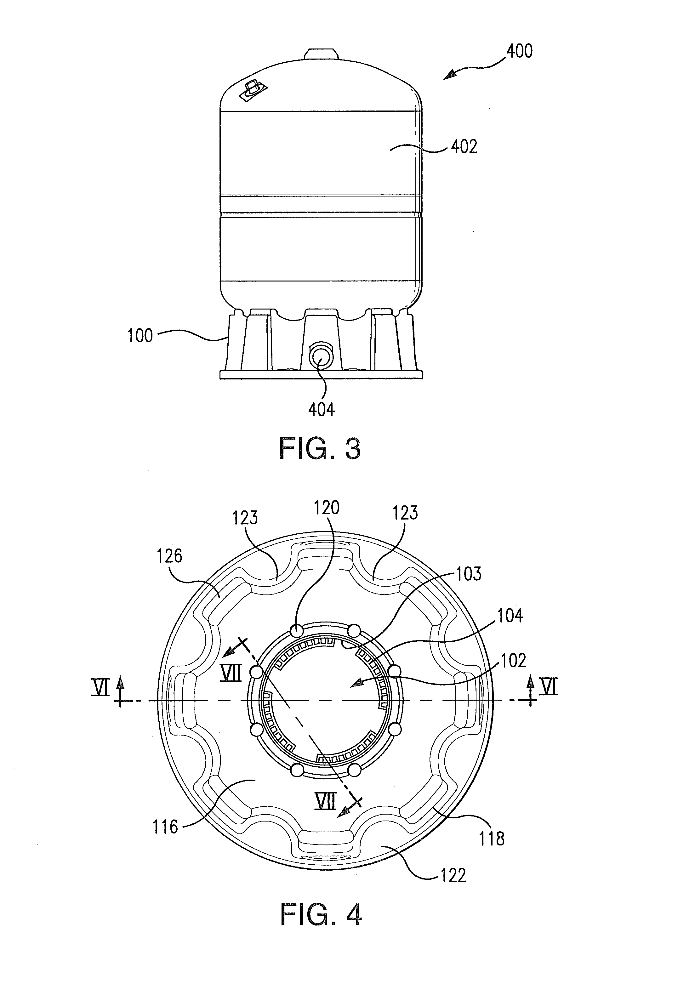
[0033]Reference will now be made to the drawings wherein like reference numerals identify similar structural features or aspects of the subject invention. For purposes of explanation and illustration, and not limitation, a partial view of an exemplary embodiment of a support stand in accordance with the invention is shown in FIG. 1 and is designated generally by reference character 100. Other embodiments of support stands in accordance with the invention, or aspects thereof, are provided in FIGS. 2-17, as will be described. The systems and methods of the invention can be used to connect a support stand to a desired pressure vessel of one or multiple different shapes while also being simple to manufacture and install.

[0034]Referring to FIG. 1, support stand 100 includes support body 114 having upper wall 116 and sidewall 118 extending downwardly from upper wall 116. Support stand 100 is formed of a corrosion-resistant material, such as a polymeric or composite material. Further, supp...


PUM


Abstract

A stand for supporting a pressure vessel includes a support body having an upper wall and a sidewall extending downwardly from the upper wall. A locking aperture is defined in the upper wall to permit passage of pressure vessel components therethrough. A plurality of locking latches is disposed along an inner dimension of the locking aperture. The locking latches are configured and adapted to couple with a pressure vessel retaining ring passing through the locking aperture.

Description

CROSS-REFERENCE TO RELATED APPLICATIONS[0001]This application claims the benefit of priority to U.S. provisional patent application 61 / 389,580, filed Oct. 4, 2010, which is incorporated by reference herein in its entirety.BACKGROUND OF THE INVENTION[0002]1. Field of the Invention[0003]The present invention relates to support stands for a pressure vessel, and more particularly to support stands which can be lockingly coupled to a pressure vessel.[0004]2. Description of Related Art[0005]Many traditional pressure vessels are constructed with a metal stand welded to one end of the vessel to mount the pressure vessel in a desired location. However, due to exposure to weather, standing water and other elements, corrosion of the metal stand can occur, and over time such metal stands can ultimately fail.[0006]Such conventional methods and systems have generally been considered satisfactory for their intended purpose. However, there is still an need in the art for a support stand that allows...

Claims


Application Information

Patent Timeline
IPC IPC(8): F17C13/08F16M11/04
CPCF16M11/04F17C13/084F17C13/083F17C2201/0109F17C2201/032F17C2205/0126F17C2205/018
Inventor MANSER, ROGERVAN HAAREN, CHRISTOPHER A.
Owner AMTROL LICENSING INC
Why Eureka
Try Eureka