Alternating frequency time domain approach to calculate the forced response of drill strings

Active Publication Date: 2014-08-21
BAKER HUGHES INC
View PDF3 Cites 8 Cited by
  • Summary
  • Abstract
  • Description
  • Claims
  • Application Information

AI Technical Summary

Benefits of technology

[0002]Disclosed is a method for estimating a steady state response of a drill string disposed in a borehole penetrating at least one of the earth and another material. The method includes calculating a first displacement of the drill string in a frequency domain for a first excitation force frequency and a number of multiples of this frequency using an equation of motion of the drill string that is solved by a processor. The equation of motion has a static force component, an excitation force component, and a non-linear force component with respect to at least one of a deflection and a derivative of the deflection of the drill string. The method further includes transforming the first displacement from the frequency domain into a time domain using the processor; calculating a non-linear force in the time domain based on at least one of the calculated displacement and a derivative of the calculated displacement using the processor; calculating a frequency domain coefficient derived from the calculated non-linear force in the time domain using the processor; and calculating a second displacement of the drill string in the frequency domain using the equation of motion and the frequency domain coefficient using the processor.
[0003]Also disclosed is a method for drilling a borehole penetrating an earth formation. The method includes: drilling a borehole with a drill rig that operates a drill string having a drill bit; obtaining borehole geometry data; and calculating a first displacement of the drill string in a frequency domain for a first excitation force frequency using an equation of motion of the drill string that is solved by a processor. The equation of motion has a static force component, an excitation force component, and a non-linear force component with respect to at least one of a deflection and a derivative of the deflection of the drill string. The method further includes: transforming the first displacement from the frequency domain into a time domain using the processor; calculating a non-linear force in the time domain based on the borehole geometry data and at least one of the calculated displacement and a der

Problems solved by technology

As the borehole is drilled deep into the earth, the drill string may bend and vibrate due to force imbalances on the drill strin

Method used


Image

  • Alternating frequency time domain approach to calculate the forced response of drill strings
  • Alternating frequency time domain approach to calculate the forced response of drill strings
  • Alternating frequency time domain approach to calculate the forced response of drill strings

Examples


Embodiment Construction

[0013]A detailed description of one or more embodiments of the disclosed apparatus and method presented herein by way of exemplification and not limitation with reference to the figures.

[0014]Disclosed are method and apparatus for mathematically modeling motion of a drill string rotating in a borehole. The method calculates a steady-state response of the drill string while considering non-linear contact forces with the borehole wall. The method employs aspects of a Multi-Harmonic Balance Method and an Alternating Frequency Time Domain Method to accurately model the dynamics of the drill string. Once the steady state response is calculated, one or more drilling parameters may be adjusted to minimize vibration of the drill string.

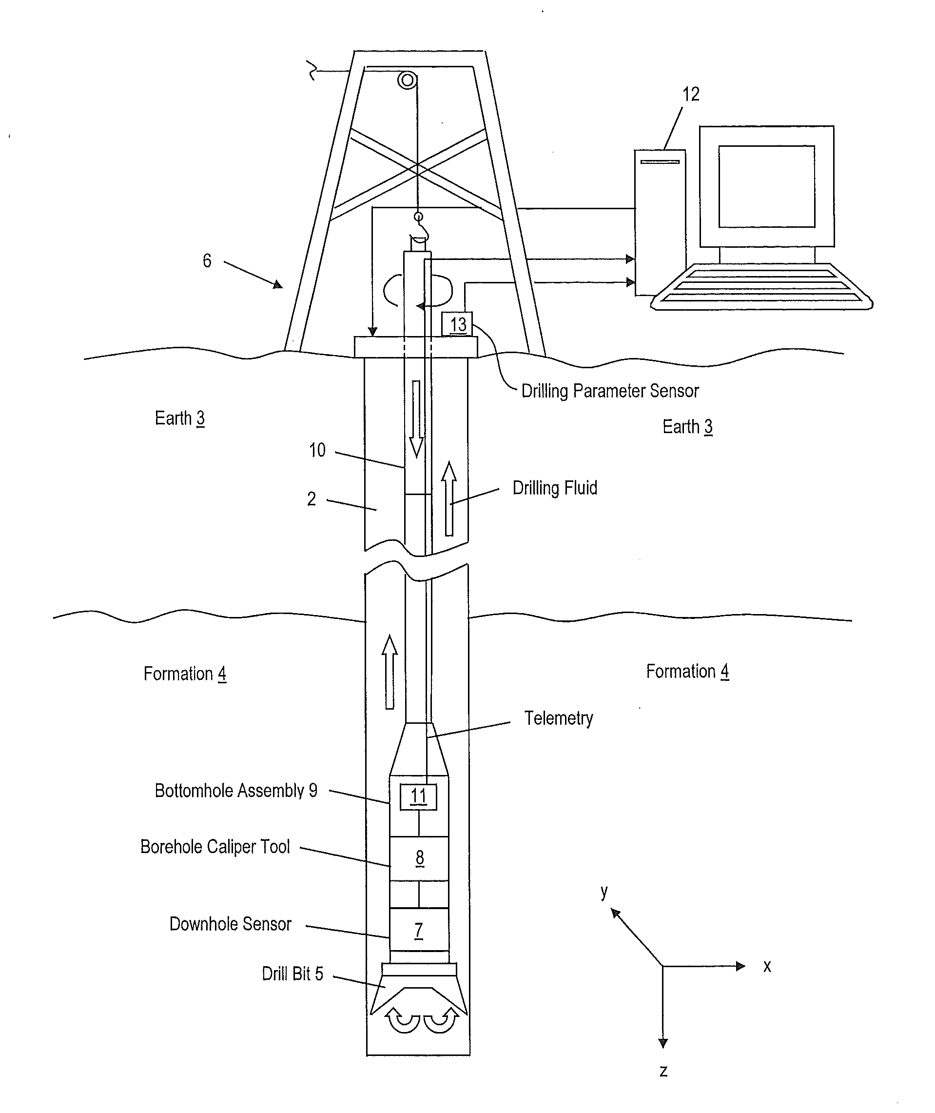
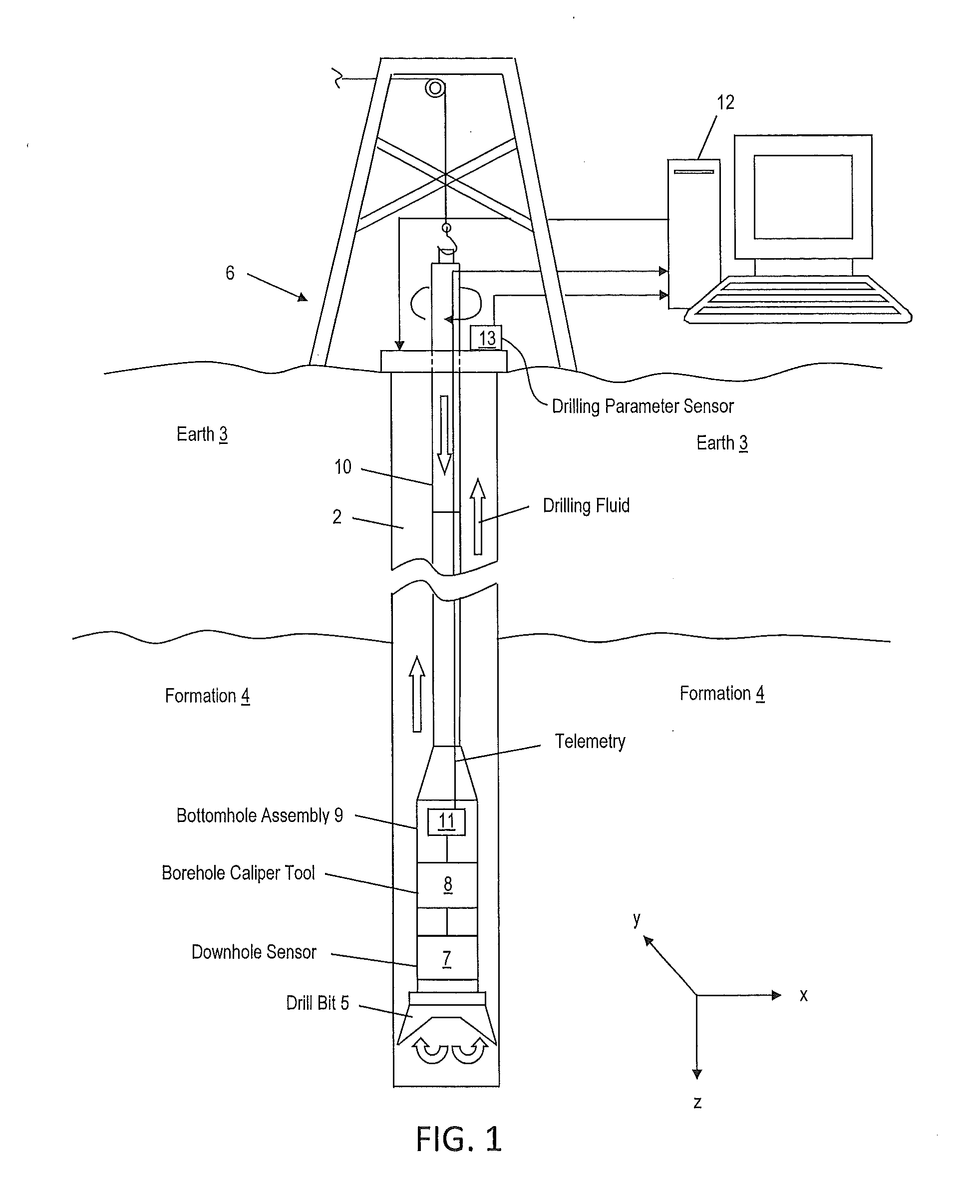
[0015]FIG. 1 illustrates a cross-sectional view of an exemplary embodiment of a drill string 10 disposed in a borehole 2 penetrating the earth 3, which may include an earth formation 4. The formation 4 represents any subsurface material of interest, such as a...


PUM


Abstract

A method for estimating a steady state response of a drill string in a borehole includes calculating a first displacement of the drill string in a frequency domain for a first excitation force frequency and a number of multiples of this frequency using an equation of motion of the drill string. The equation of motion has a static force component, an excitation force component, and a non-linear force component with respect to at least one of a deflection and a derivative of the deflection of the drill string. The method further includes: transforming the first displacement from the frequency domain into a time domain; calculating a non-linear force in the time domain; calculating a frequency domain coefficient derived from the calculated non-linear force in the time domain; and calculating a second displacement of the drill string in the frequency domain using the equation of motion and the frequency domain coefficient.

Description

BACKGROUND[0001]Boreholes are drilled into the earth for various reasons such as exploration and production for hydrocarbons and geothermal energy in addition to sequestration of carbon dioxide. A borehole is typically drilled using a drill bit disposed at the distal end of a series of connected drill pipes referred to as a drill string. A drill rig rotates the drill string, which rotates the drill bit, to cut into the earth to create the borehole. As the borehole is drilled deep into the earth, the drill string may bend and vibrate due to force imbalances on the drill string. Excessive vibrations can delay drilling and possibly cause damage, both of which may significantly affect the cost of drilling. Hence, it would be appreciated in the drilling industry if a method could be developed to mathematically model a drill string with high physical accuracy and in real time in order to improve drilling efficiency.BRIEF SUMMARY[0002]Disclosed is a method for estimating a steady state res...

Claims


Application Information

Patent Timeline
IPC IPC(8): E21B47/16
CPCE21B47/16E21B17/00E21B41/00E21B47/00E21B47/007E21B44/02E21B47/12
Inventor HOHL, ANDREASSCHUBERTH, FRANKRECKMANN, HANNO
Owner BAKER HUGHES INC
Why Eureka
Try Eureka