Image capture apparatus and method for controlling the same

a technology of image capture and image, applied in the field of image capture apparatus, can solve the problems of missing parts of the corrected image, the inability to correctly perform a correction requiring the reference area, and the inability to correct so as to achieve the effect of correcting the blurring of an imag

Active Publication Date: 2014-08-21
CANON KK
View PDF2 Cites 10 Cited by
  • Summary
  • Abstract
  • Description
  • Claims
  • Application Information

AI Technical Summary

Benefits of technology

[0014]The present invention has been made in view of such problems of the conventional art, and it is an objective to provide an image capture apparatus and a method for controlling the same that can effectively correct blurring (image shake) of an image due to a motion of the image capture apparatus by combining an optical image shake correction and a geometric deformation process.

Problems solved by technology

If the necessary reference area is not included in the imaging area (captured image), it is impossible to correctly perform a correction requiring the reference area, and in some cases, a part of the corrected image is missing.
Therefore, if a geometric deformation process is performed on an image that has been subjected to correction of image shake due to translational direction components of a shake, it is possible that a reference area necessary for the geometric deformation process is not included in the imaging area (area of a captured image held in a memory), and that a part of the corrected image is missing.
Thus, there has been a case where an ability to correct image shake due to rotational direction components of a shake by geometric deformation processing is not effective when capturing an image in an imaging area larger than a record size.

Method used


Image

  • Image capture apparatus and method for controlling the same
  • Image capture apparatus and method for controlling the same
  • Image capture apparatus and method for controlling the same

Examples


first embodiment

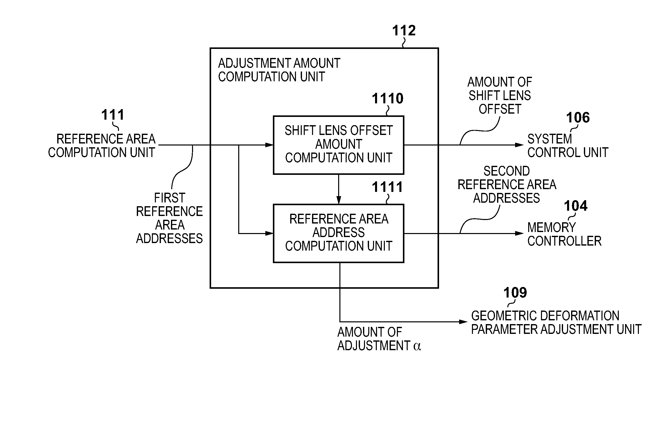
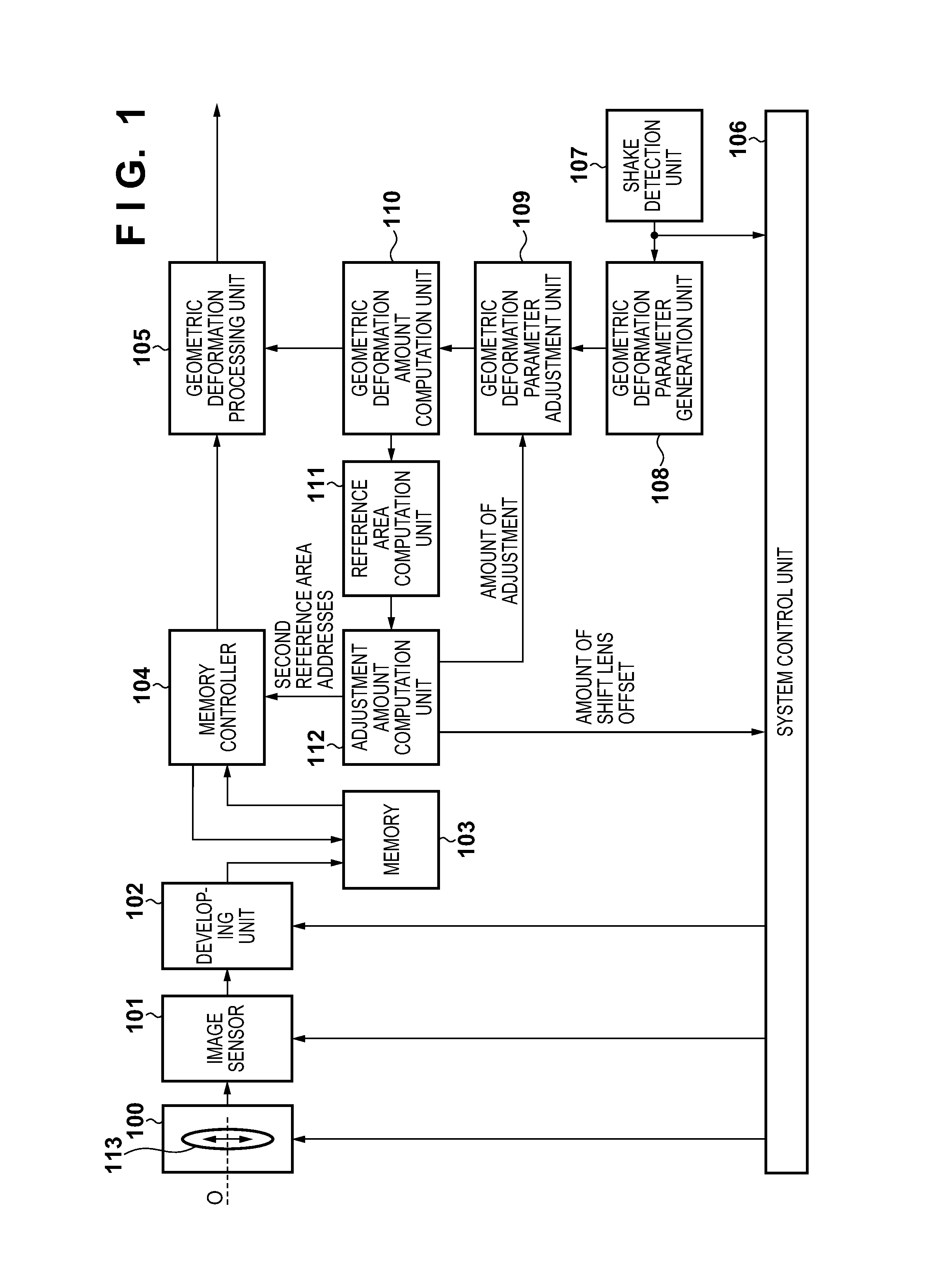
[0030]FIG. 1 is a block diagram showing a functional configuration example of a digital camera serving as one example of an image processing apparatus according to a first embodiment of the present invention. In the present embodiment, although a case will be described where an optical member for realizing optical image shake corrections is a shift lens, the embodiment can likewise be carried out even when a sensor shift method of moving an image sensor is used.

[0031]An optical system 100 includes a shift lens 113. The shift lens 113 is movable in directions (orthogonal directions or rotational directions whose rotation centers are on the optical axis) non-parallel to the optical axis O of the optical system 100, which mitigates image shake due to translational direction components of a motion (shake) of the apparatus. An image sensor 101 converts, into image signals, an optical image formed through the optical system 100. A developing unit 102 performs, on image signals from the im...

second embodiment

[0088]FIG. 9 is a block diagram showing a functional configuration example of a digital camera serving as one example of an image capture apparatus according to a second embodiment of the present invention. In FIG. 9, function blocks that are identical with function blocks in FIG. 1 are marked with identical reference numerals, and the duplicate description is omitted. As can be seen by comparing FIG. 9 with FIG. 1, a digital camera according to the present embodiment is different from that according to the first embodiment in that the digital camera includes an offset amount predicting unit 114 predicting the amount of shift lens offset.

[0089]Hereinafter, parts different from the first embodiment about a configuration and an operation of a digital camera according to the present embodiment will be mainly described.

[0090]Angular velocity information from the shake detection unit 107 corresponds to time at which an image to be subjected to a geometric deformation process is captured,...


PUM


Abstract

An offset corresponding to an amount of geometric deformation is added to an amount of drive of an optical member due to an optical image shake correction so that the center of a reference area necessary for geometric deformation processing comes closer to the center of an imaging area. Because of this, a possibility is increased that a reference area necessary for geometric deformation processing is fully contained in an imaging area, and blurring of an image due to a motion of an image capture apparatus is effectively corrected by combining an optical image shake correction and a geometric deformation process.

Description

BACKGROUND OF THE INVENTION[0001]1. Field of the Invention[0002]The present invention relates to an image capture apparatus and a method for controlling the same, and in particular, to image shake correction technique for suppressing image shake caused by a motion of an image capture apparatus, such as camera shake.[0003]2. Description of the Related Art[0004]Conventionally, so-called image shake correction functions are known that correct (mitigate) blurring (image shake) of a captured image caused by a motion of an image capture apparatus, and optical image shake correction and electronic image shake correction are typical methods for realizing image shake correction functions (see Japanese Patent Laid-Open No. 2011-145604). Optical image shake correction is a method for suppressing a motion of an object image by a moving optical member such as a shift lens or an image sensor, based on a detected amount of shake of an image capture apparatus. In addition, electronic image shake co...

Claims


Application Information

Patent Timeline
Patent Type & Authority Applications(United States)
IPC IPC(8): H04N5/232
CPCH04N5/23254H04N23/683H04N23/685H04N23/6811
Inventor TAKAYAMA, KAZUNORI
Owner CANON KK
Why Eureka
Try Eureka