
Fiber scanning projector

a fiber scanning and projector technology, applied in the field of subminiature projectors, can solve the problems of color breakage, reducing light efficiency, and bulky structure of three-panel projectors

Active Publication Date: 2014-08-21
SAMSUNG ELECTRONICS CO LTD
View PDF3 Cites 79 Cited by
  • Summary
  • Abstract
  • Description
  • Claims
  • Application Information

AI Technical Summary

Benefits of technology

The patent describes a fiber scanning projector that uses a light source and a scanner to project images onto a screen. The scanner includes a fiber bundle and an actuator that is controlled by a synchronization controller. The actuator includes piezoelectric strips that are attached to the fiber bundle and a power supply to drive the strips. The scanner can be controlled to scan the screen in two directions. The projector can also include a varifocal lens and an asymmetric structure to improve image quality. Additionally, the patent describes a fiber scanning 3D image projector that uses multiple fiber scanning projectors to form a 3D image.

Problems solved by technology

That is, due to a great number of employed optical components, the three panel type projector has a bulky structure.
The single panel type projector uses a light source for emitting a white light, and a color wheel for time-sequentially dividing the emitted white light into red, green, and blue lights, thereby reducing light efficiency and causing color break-up.

Method used


Image

  • Fiber scanning projector
  • Fiber scanning projector
  • Fiber scanning projector

Examples


Embodiment Construction

[0042]Reference will now be made in detail to exemplary embodiments, examples of which are illustrated in the accompanying drawings, wherein like reference numerals refer to like elements throughout. In the drawings, the sizes of the elements are exaggerated for clarity of illustration and are not limited to illustrated shapes.

[0043]In this regard, the present exemplary embodiments may have different forms and should not be construed as being limited to the descriptions set forth herein. Accordingly, the exemplary embodiments are merely described below, by referring to the figures, to explain aspects of the present description. As used herein, the term “and / or” includes any and all combinations of one or more of the associated listed items.

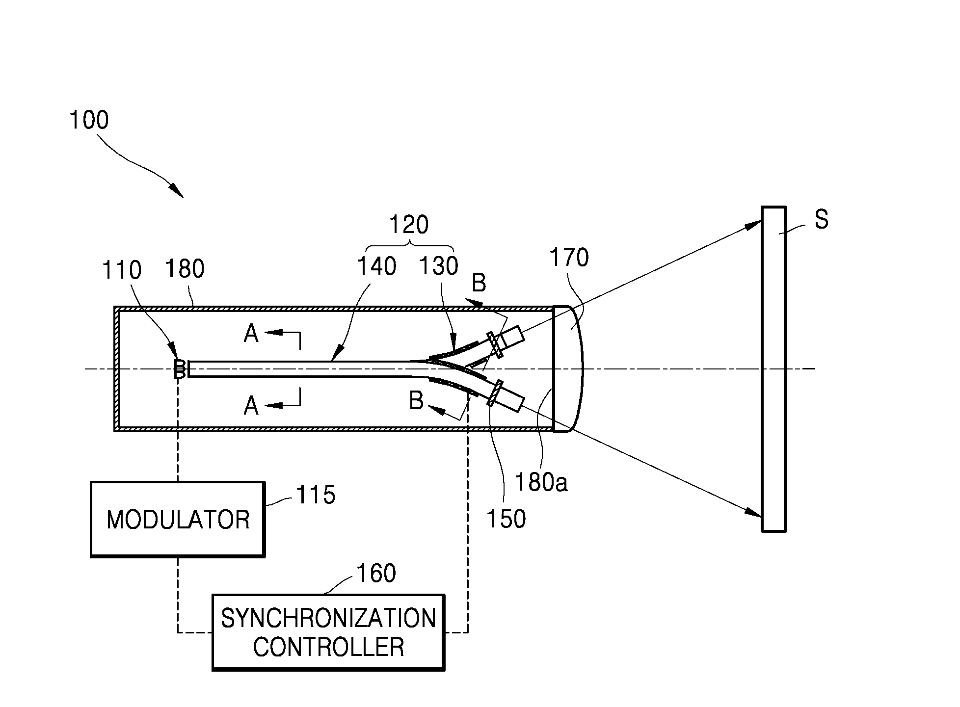
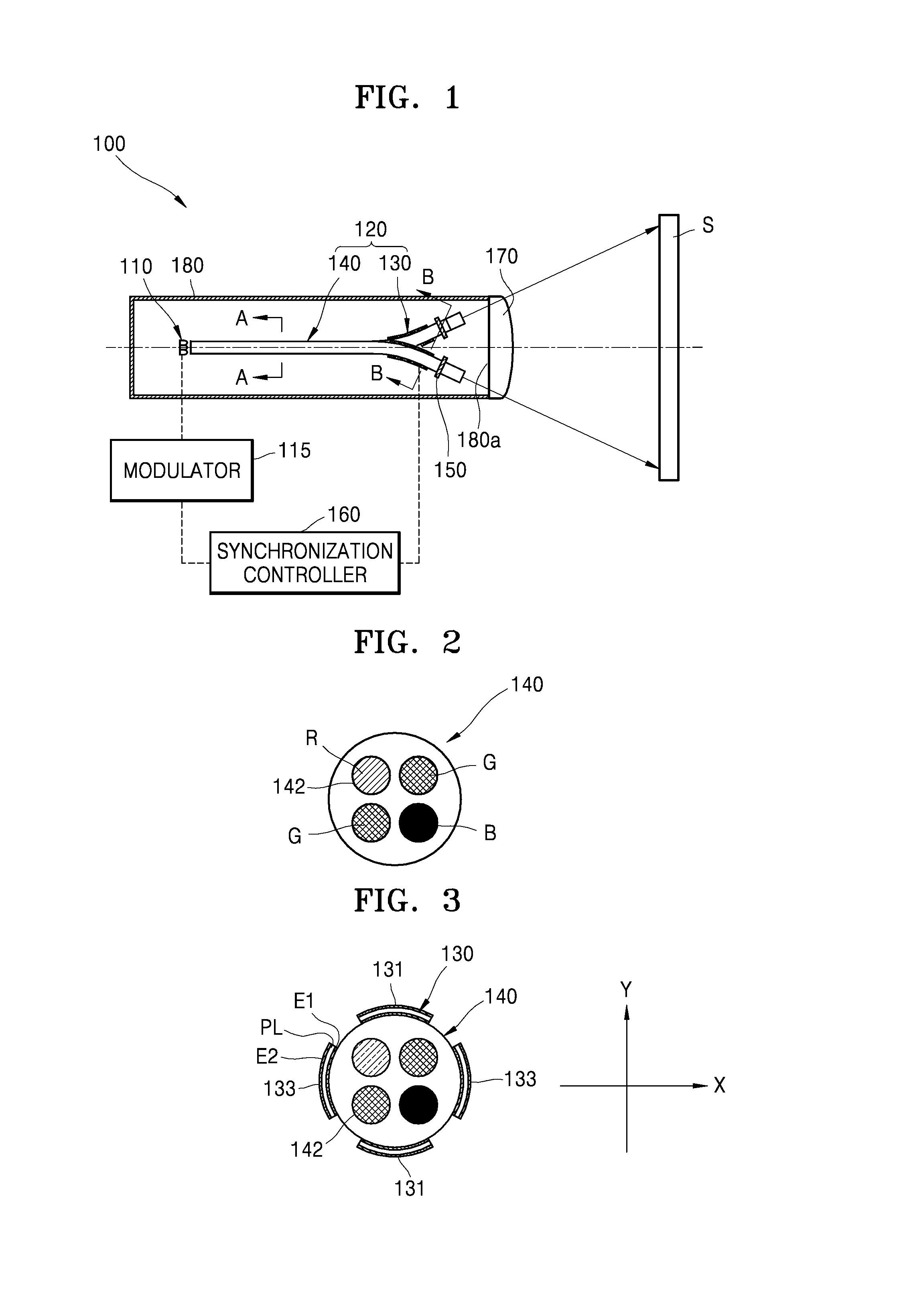
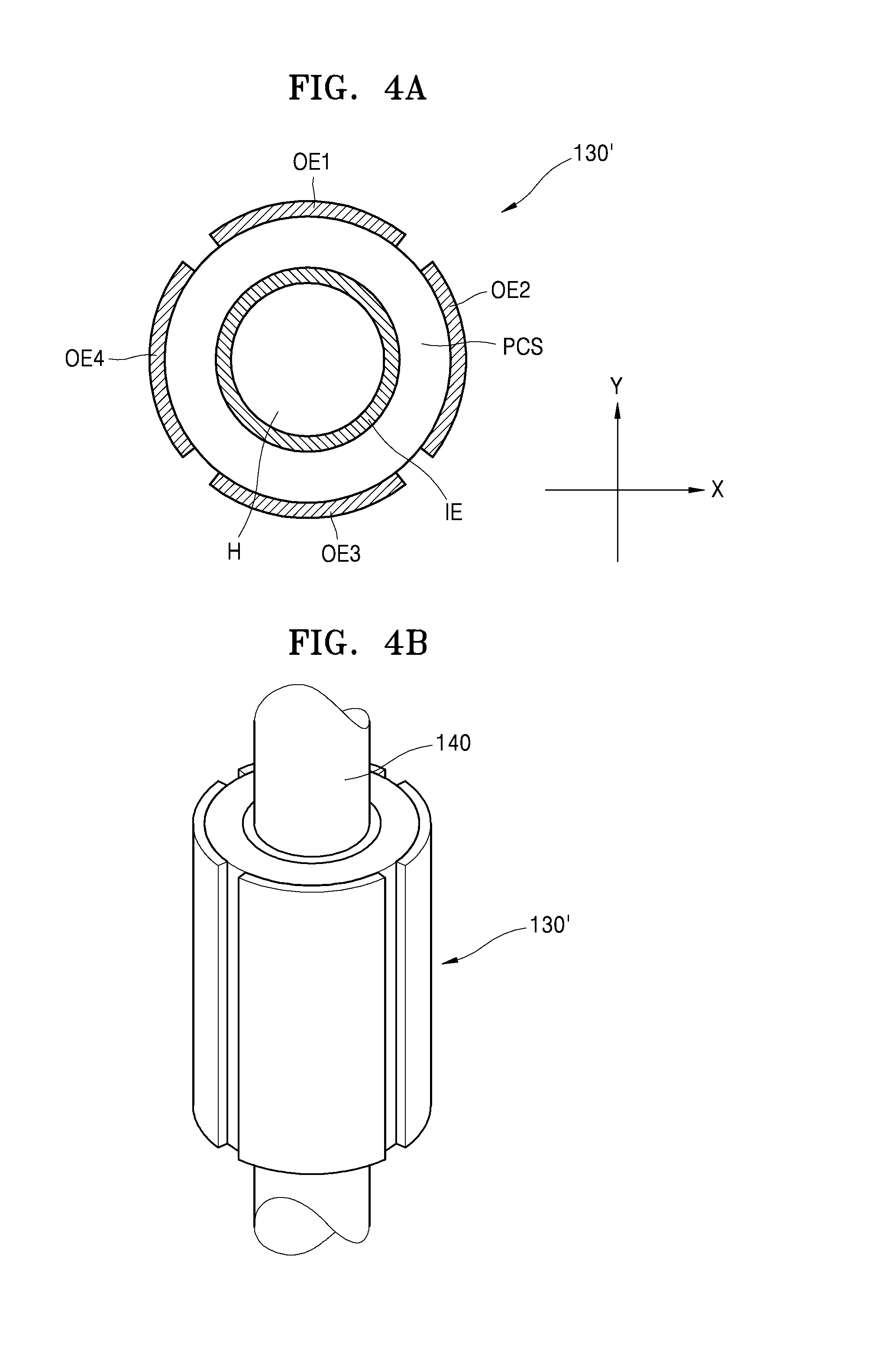
[0044]FIG. 1 is a cross-sectional view of a schematic configuration of a fiber scanning projector 100 according to an exemplary embodiment, FIG. 2 is a cross-sectional view taken along line A-A in FIG. 1, and FIG. 3 is a cross-sectional view taken...


PUM


Abstract

A fiber scanning projector includes a light source comprising a plurality of monochromatic light sources, a modulator providing a modulation signal according to image information to the light source, a scanner scanning a screen with a light emitted from the light source and controlled according to the modulation signal, the scanner including a fiber bundle and an actuator which 2-axis-drives the fiber bundle, and a synchronization controller synchronizing driving of the actuator and driving of the modulator.

Description

CROSS-REFERENCE TO RELATED APPLICATIONS[0001]This application claims priority from Korean Patent Application No. 10-2013-0016599, filed on Feb. 15, 2013, in the Korean Intellectual Property Office, the disclosure of which is incorporated herein in its entirety by reference.BACKGROUND[0002]1. Field[0003]Methods and apparatuses consistent with the exemplary embodiments relate to subminiature projectors in a fiber scanning scheme, and a fiber scanning projector which has a high light efficiency by using a scheme of scanning each pixel with a plurality of monochromatic light sources, and adopts a 2-axis-driving fiber scanning scheme.[0004]2. Description of the Related Art[0005]A projector is a device for modulating a light according to a video signal, and projecting the modulated light onto a screen. According to a light modulating device, projectors are classified into a digital light processing (DLP) projector, a liquid crystal on silicon (LCOS) projector, a micro-electromechanical sy...

Claims


Application Information

Patent Timeline
Patent Type & Authority Applications(United States)
IPC IPC(8): H04N9/31
CPCH04N9/3135H04N9/3129H04N9/3173G03B21/00G03B21/14G02B26/103G03B21/2033
Inventor KIM, WOON-BAE
Owner SAMSUNG ELECTRONICS CO LTD
Learn More