Method and system for fiber optic determination of gas concentrations in liquid receptacles

a technology of liquid receptacles and fiber optics, which is applied in the direction of optical radiation measurement, instruments, spectrometry/spectrophotometry/monochromators, etc., can solve the problems of ineffective technique for reliable measurement of oxygen concentration, sensor prone to large drift, and fire hazards

Inactive Publication Date: 2008-06-10
NASA UNITED STATES OF AMERICA THE AS REPRESENTED BY THE ADMINISTATOR OF
View PDF17 Cites 78 Cited by
  • Summary
  • Abstract
  • Description
  • Claims
  • Application Information

AI Technical Summary

Problems solved by technology

One such issue of determination of compositions of gaseous materials occurs with fuel tanks.
However, the first two techniques above require exposing the ullage gases to a sensor that is connected to a wire which can potentially be a source of sparks or electrostatic ignition.
Furthermore, the electrochemical sensor typically uses a heated element that reacts and consumes the oxygen that it is sensing, producing a fire hazard.
The fiber optic fluorescence quenching sensors that utilize the intensity of an oxygen sensitive dye that is illuminated with a blue LED have also been proposed but this sensor is prone to large drifts when exposed to temperature changes.
The drift of the fluorescence quenching type sensor is so great that it renders the technique ineffective for the reliable measurement of oxygen concentration in the ullage of a fuel tank.
The diode laser absorption technique is problematic because it requires a diode laser to tune and lock onto specific oxygen absorption lines, the technique requires windows for optical access which can get dirty from fuel deposits.
None of these techniques can measure both nitrogen and oxygen concentration to provide an accurate mixing ratio without having to assume that the balance is nitrogen.
Also, none of these other techniques are able to provide fuel vapor concentration.

Method used


Image

  • Method and system for fiber optic determination of gas concentrations in liquid receptacles
  • Method and system for fiber optic determination of gas concentrations in liquid receptacles
  • Method and system for fiber optic determination of gas concentrations in liquid receptacles

Examples


Embodiment Construction

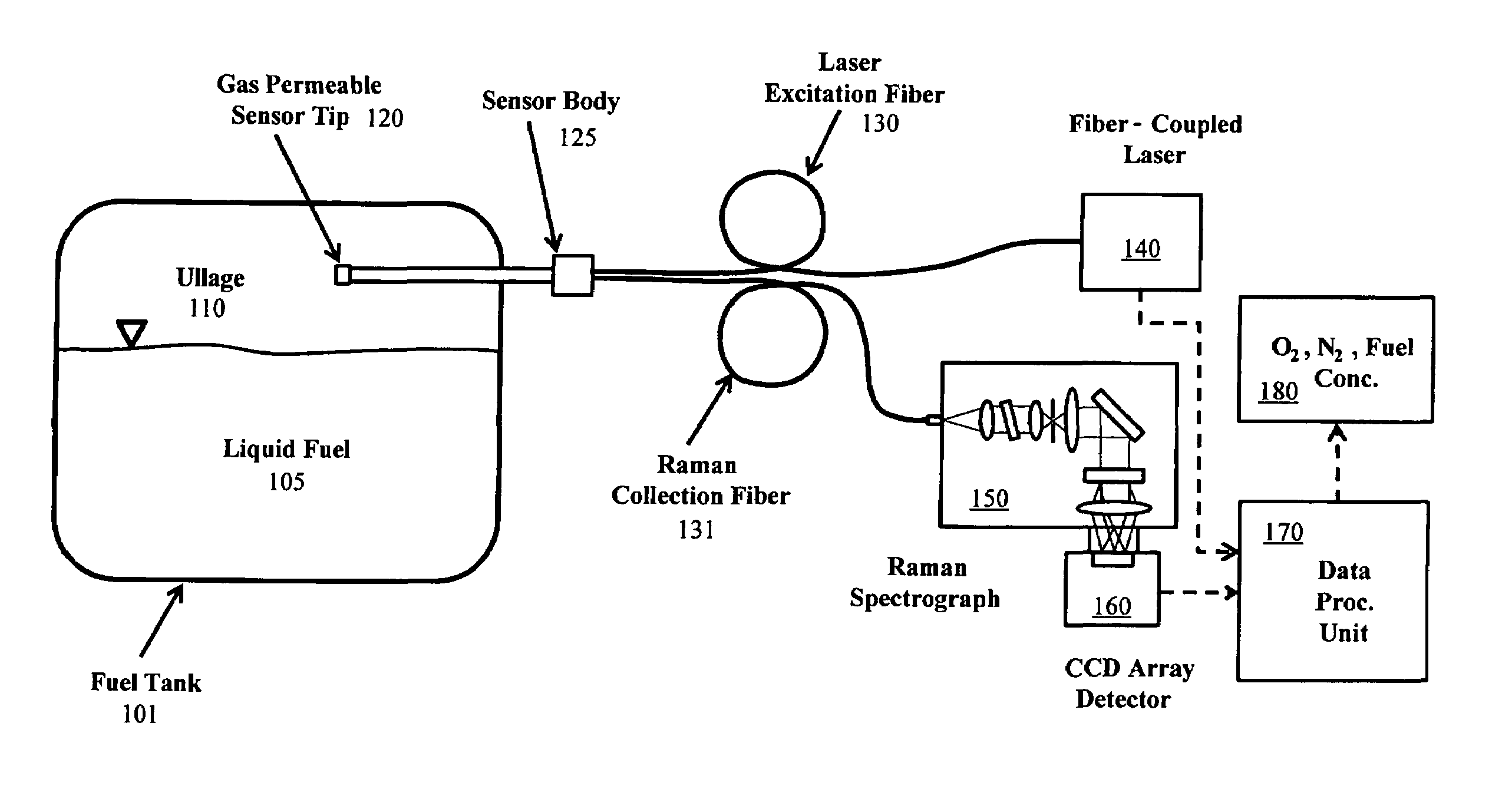
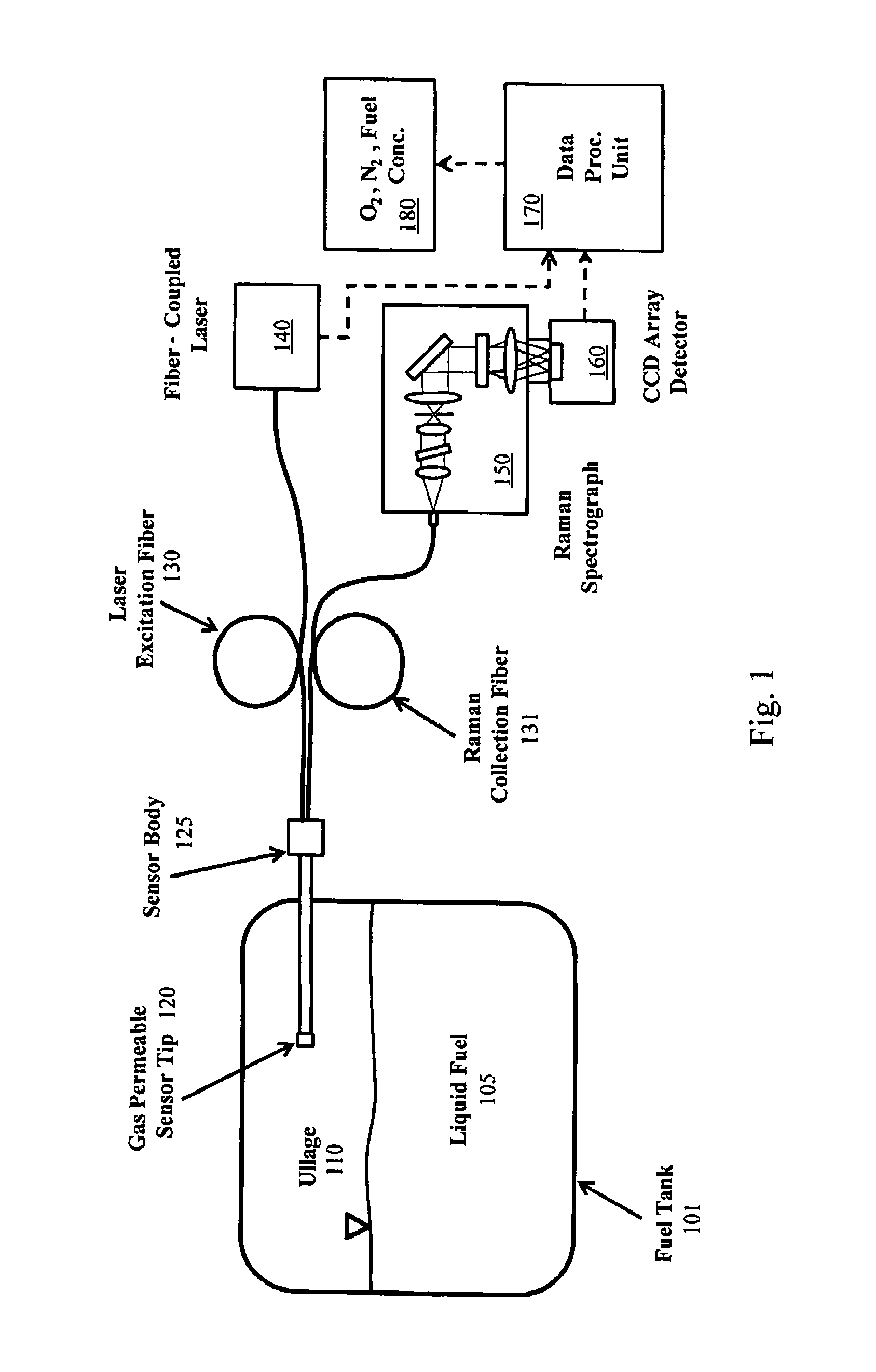
[0036]The present invention seeks to provide quantitative and accurate measurements of the compositions of gaseous materials in liquid receptacles. The present invention also seeks, in one embodiment, to provide a quantitative and accurate measurement of the concentration of nitrogen, oxygen, and fuel vapor in the ullage of a fuel tank. This information is needed in order to provide control information for an OBIGGS, and also for the determination of the appropriate levels of inerting required for safety. The ullage gas sensor system is based on spontaneous vibrational laser Raman scattering from the species of interest. Raman scattering is used because it is one of the few optical techniques that permits the simultaneous multi-species measurements of chemical concentrations.

[0037]The system provides an accurate and quantitative identification of the above gases with an accuracy of better than 1% (by volume) over approximately a 1 minute time duration. The technology described in th...


PUM

PropertyMeasurementUnit
pressureaaaaaaaaaa
pressureaaaaaaaaaa
full-width-half-maxaaaaaaaaaa

Abstract

A system for determining gas compositions includes a probe, inserted into a source of gaseous material, the probe having a gas permeable sensor tip and being capable of sending and receiving light to and from the gaseous material, a sensor body, connected to the probe, situated outside of the source and a fiber bundle, connected to the sensor body and communicating light to and from the probe. The system also includes a laser source, connected to one portion of the fiber bundle and providing laser light to the fiber bundle and the probe a Raman spectrograph, connected to another portion of the fiber bundle, receiving light from the probe and filtering the received light into specific channels and a data processing unit, receiving and analyzing the received light in the specific channels and outputting concentration of specific gas species in the gaseous material based on the analyzed received light.

Description

ORIGIN OF THE INVENTION[0001]The invention described herein was made by employees of the United States Government and may be manufactured and used by or for the Government for Government purposes without payment of any royalties thereon or therefore.BACKGROUND OF THE INVENTION[0002]1. Field of Invention[0003]The present invention relates to systems for determining the chemical composition of gaseous mixtures. In particular, the present invention is directed to systems and processes for determining the presence and composition of oxygen, nitrogen and hydrocarbons, among other gaseous constituents, in gaseous mixtures. In specific embodiments, the invention allows for the use of optical spectroscopy to analyze the gaseous compositions without exposing the interiors of liquid receptacles to the outside or sources of ignition.[0004]2. Description of Related Art[0005]There are many environments where it is important to measure with great accuracy the composition of gaseous materials in r...

Claims


Application Information

Patent Timeline
Patent Type & Authority Patents(United States)
IPC IPC(8): G01J3/44G01N21/65
CPCG01J3/02G01J3/0218G01J3/0221G01J3/0227G01J3/12G01J3/28G01J3/36G01J3/44G01N21/65
Inventor NGUYEN, QUANG-VIET
Owner NASA UNITED STATES OF AMERICA THE AS REPRESENTED BY THE ADMINISTATOR OF
Why Eureka
Try Eureka