Remote wellsite material tracking

a technology for tracking and wellsites, applied in the direction of transportation items, instruments, borehole/well accessories, etc., can solve the problems of affecting the efficiency of drilling and drilling, the cost of such automation for a large number of people, and the limited scope of implementation of existing fleet of assets,

Active Publication Date: 2014-08-21
SCHLUMBERGER TECH CORP
View PDF2 Cites 95 Cited by
  • Summary
  • Abstract
  • Description
  • Claims
  • Application Information

AI Technical Summary

Problems solved by technology

However, the cost of such automation for a large, existing fleet of assets can be limiting to the scope of implementation.
Deploying the automation across a large fleet can also be limited by related maintenance costs and logistics, because assets of large fleets less frequently return to maintenance facilities when demand for the assets increases.
Past automation attempts were also plagued by the difficulties associated with the assets being resupplied across a substantial geographic area, including where asset and supply mobility became hampered by loss of wireless connectivity due to lack of line of site between assets at multiple wellsites, or even within a single wellsite.

Method used


Image

  • Remote wellsite material tracking
  • Remote wellsite material tracking
  • Remote wellsite material tracking

Examples


Embodiment Construction

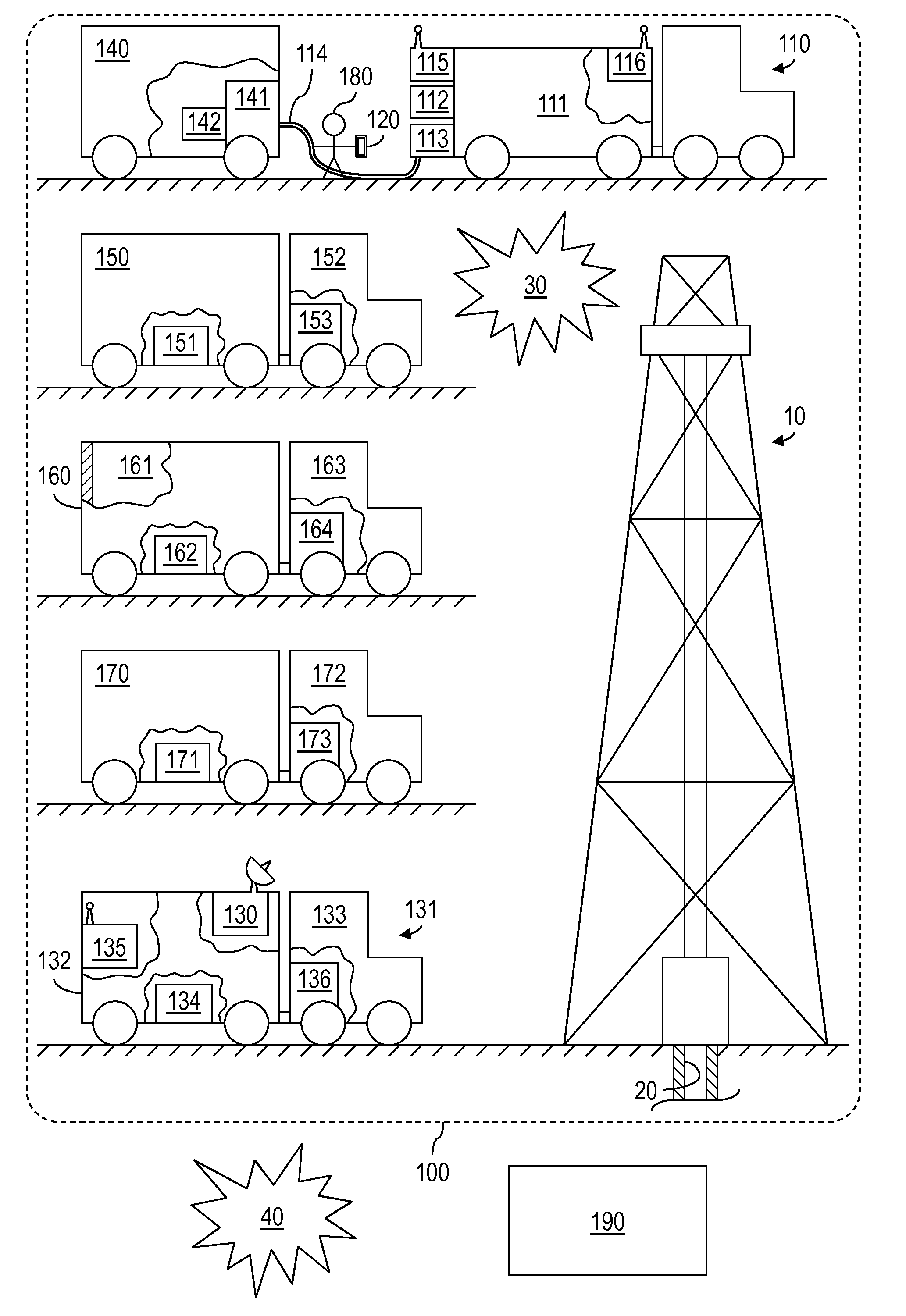
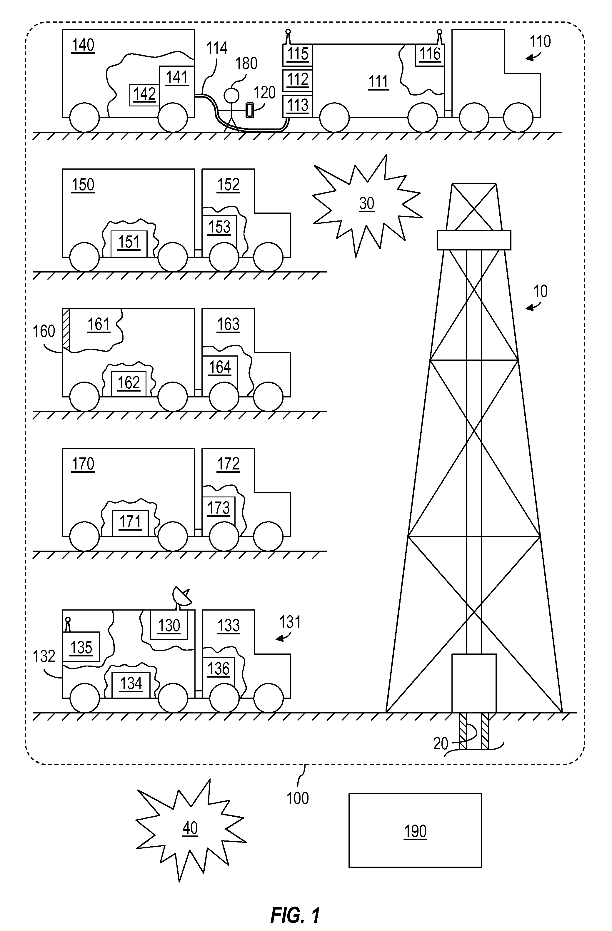
[0012]It is to be understood that the following disclosure provides many different embodiments, or examples, for implementing different features of various embodiments. Specific examples of components and arrangements are described below to simplify the present disclosure. These are, of course, merely examples and are not intended to be limiting. In addition, the present disclosure may repeat reference numerals and / or letters in the various examples. This repetition is for the purpose of simplicity and clarity and does not in itself dictate a relationship between the various embodiments and / or configurations discussed.

[0013]A person having ordinary skill in the art should also understand that, in the development of an actual embodiment within the scope of the present disclosure, numerous implementation-specific decisions may be made to achieve certain goals of the development, such as compliance with system-related and business-related constraints and other constraints that may vary...


PUM


Abstract

A wellsite system that includes a bulk material transporter, a mobile tagger, and an uplink. The bulk material transporter includes a supply of a bulk material, a meter to measure output from the supply, and a data logger to log the output as a function of a predetermined parameter. The mobile tagger assigns transfer parameters to each transfer of the bulk material from the supply to one of multiple assets located at the wellsite, including the output measured by the meter. The uplink wirelessly transmits data from the log and the transfer parameters to remote data storage not located at the wellsite.

Description

CROSS-REFERENCE TO RELATED APPLICATIONS[0001]This application claims the benefit of U.S. Provisional Application No. 61 / 767,794, entitled “SYSTEM AND METHOD FOR RECORDING BULK MATERIAL DELIVERY AT A WELLSITE,” filed Feb. 21, 2013, the entire disclosure of which is hereby incorporated herein by reference.BACKGROUND OF THE DISCLOSURE[0002]The drilling and operation of oil and gas wells generally occurs at a wellsite at which machinery, tanks, vehicles, and other physical assets are stationed for an extended period of time. Many of the physical assets utilize various consumables, such as fuel, water, and sand. In an effort to reduce related costs and errors attributable to human workers at the wellsite, various attempts have been made to automate the management of usage, supply levels, and resupplies of the consumables. However, the cost of such automation for a large, existing fleet of assets can be limiting to the scope of implementation. Deploying the automation across a large fleet...

Claims


Application Information

Patent Timeline
Patent Type & Authority Applications(United States)
IPC IPC(8): E21B41/00B60P1/00
CPCB60P1/00E21B41/0092B60P3/14Y02P90/845
Inventor THOMEER, HUBERTUS V.
Owner SCHLUMBERGER TECH CORP
Why Eureka
Try Eureka