Treadmill

a technology of treadmill applied in the field of treadmills, can solve the problems of reducing the lifespan, wasting energy, and consuming electrical energy, and achieve the effects of preventing safety accidents of exercisers, reducing friction resistance between running belts and support decks, and saving driving energy for rotation

Active Publication Date: 2014-08-21
LEE BYUNG DON
View PDF1 Cites 7 Cited by
  • Summary
  • Abstract
  • Description
  • Claims
  • Application Information

AI Technical Summary

Benefits of technology

[0018]The treadmill according to the embodiment of the present invention has the following effects.
[0019]First, as the support deck is configured to be movable forward and rearward by interlocking with rotation of the running belt and running motion of an exerciser, frictional resistance between the running belt and the support deck can be minimized to save driving energy for rotation of the running belt.
[0020]Second, power can be generated using a propulsive force generated when an exerciser pushes the running belt rearward with his / her feet upon running of the exerciser.
[0021]Third, as an auxiliary support unit is installed inside the running belt, when an exerciser steps up on an upper rear portion of the running belt to perform exercise, damage to the running belt due to depression downward caused by the weight of the exerciser and a safety accident of the exerciser can be prevented.

Problems solved by technology

That is, in the treadmill of the related art, the running belt rotating while the exerciser walks or runs comes in contact with the fixed support deck 10a, a frictional load occurs whenever such contacts occur, and thus, consumption of electrical energy of the driving motor 5 due to an increase in frictional load is increased to cause waste of energy.
In addition, an excessive load is applied to a bearing configured to support a rotary shaft of the driving motor 5 and the running belt 8 to reduce the lifespan thereof.

Method used


Image

  • Treadmill
  • Treadmill
  • Treadmill

Examples


Embodiment Construction

[0033]Hereinafter, an embodiment of the present invention will be described in detail with reference to the accompanying drawings. However, the present invention is not limited to the embodiment to be described below but may be implemented in various different types. The embodiment is merely provided to completely disclose the present invention and completely inform those skilled in the art of the spirit of the present invention. Like reference numerals in the drawings designate like element.

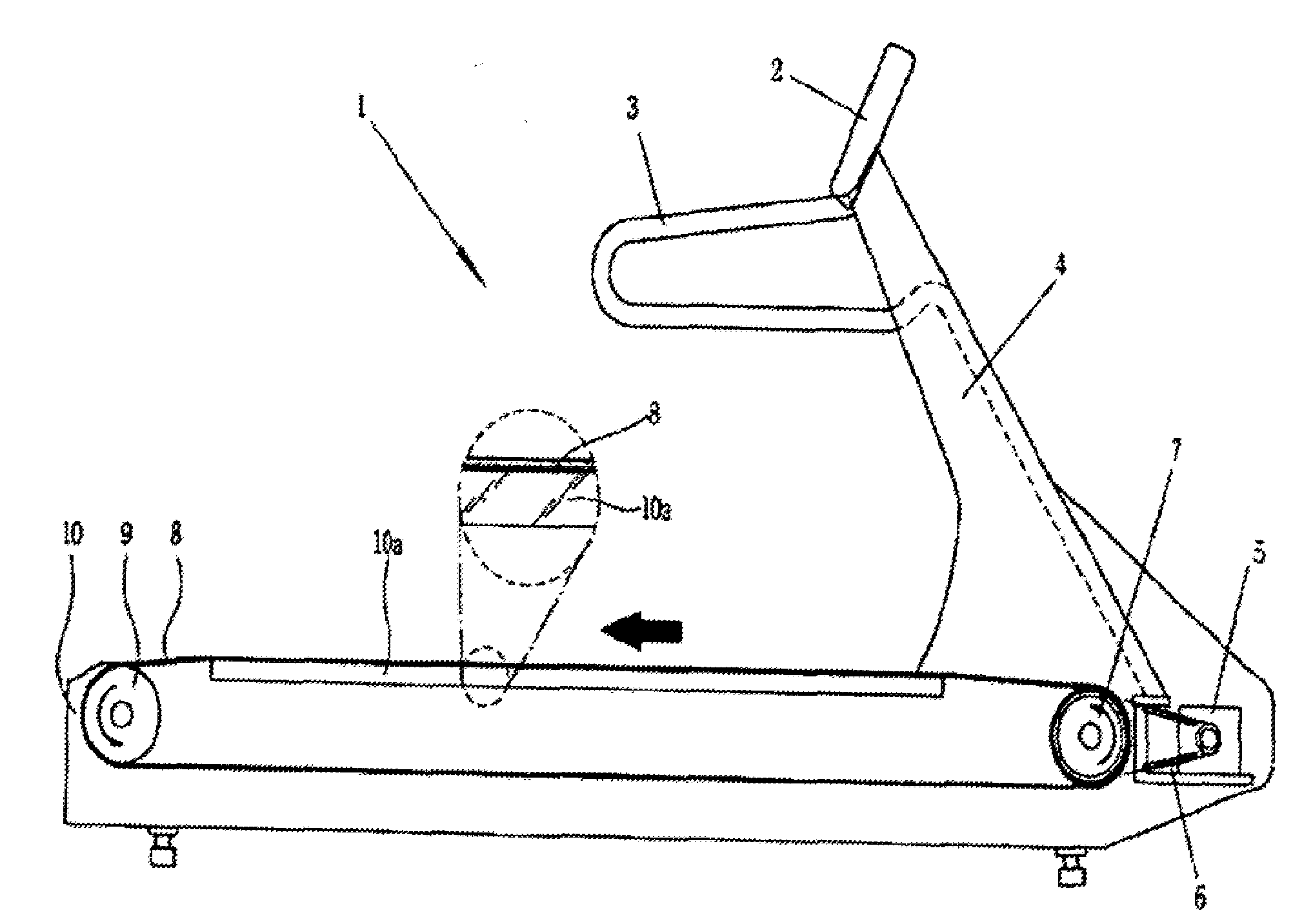
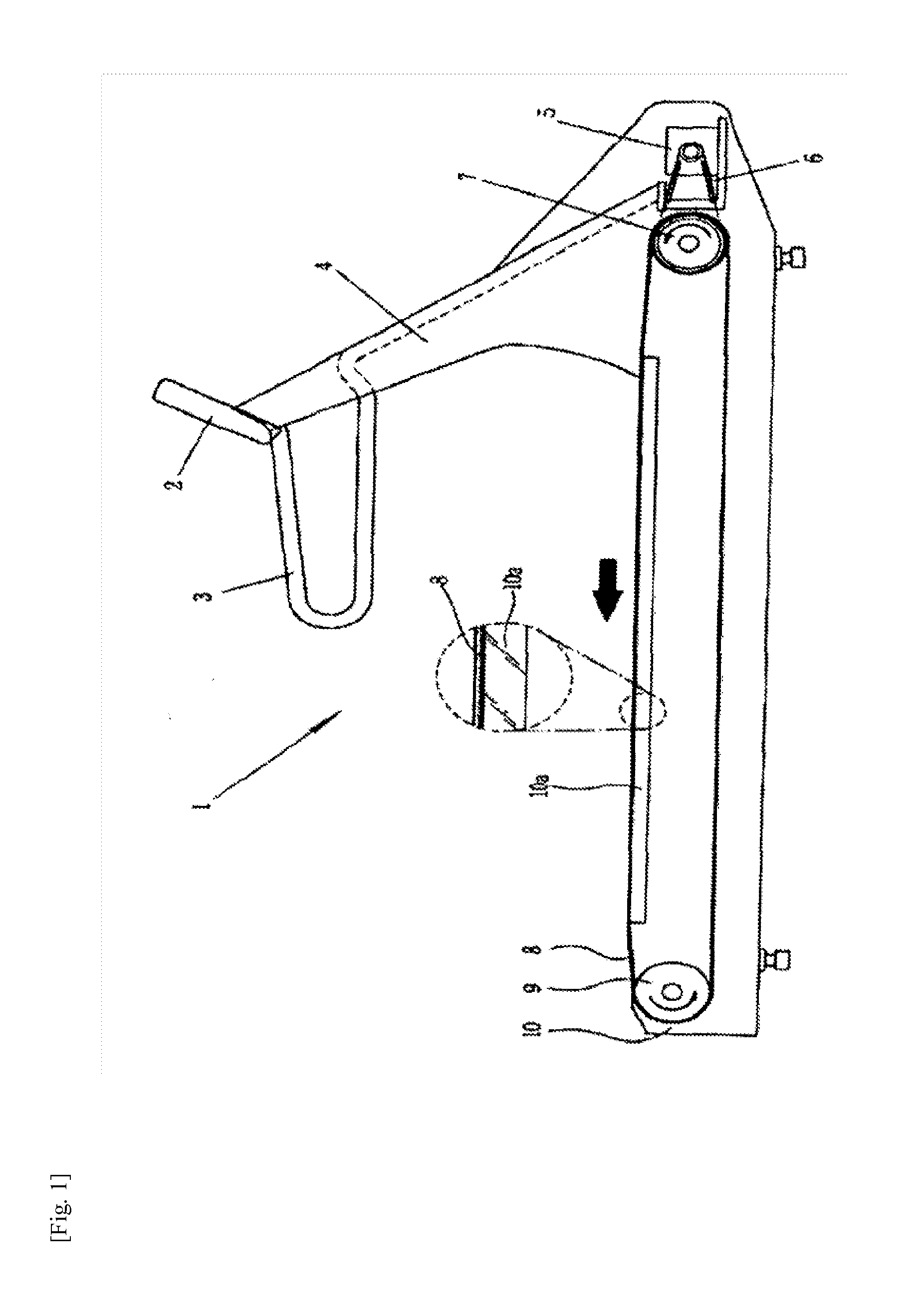
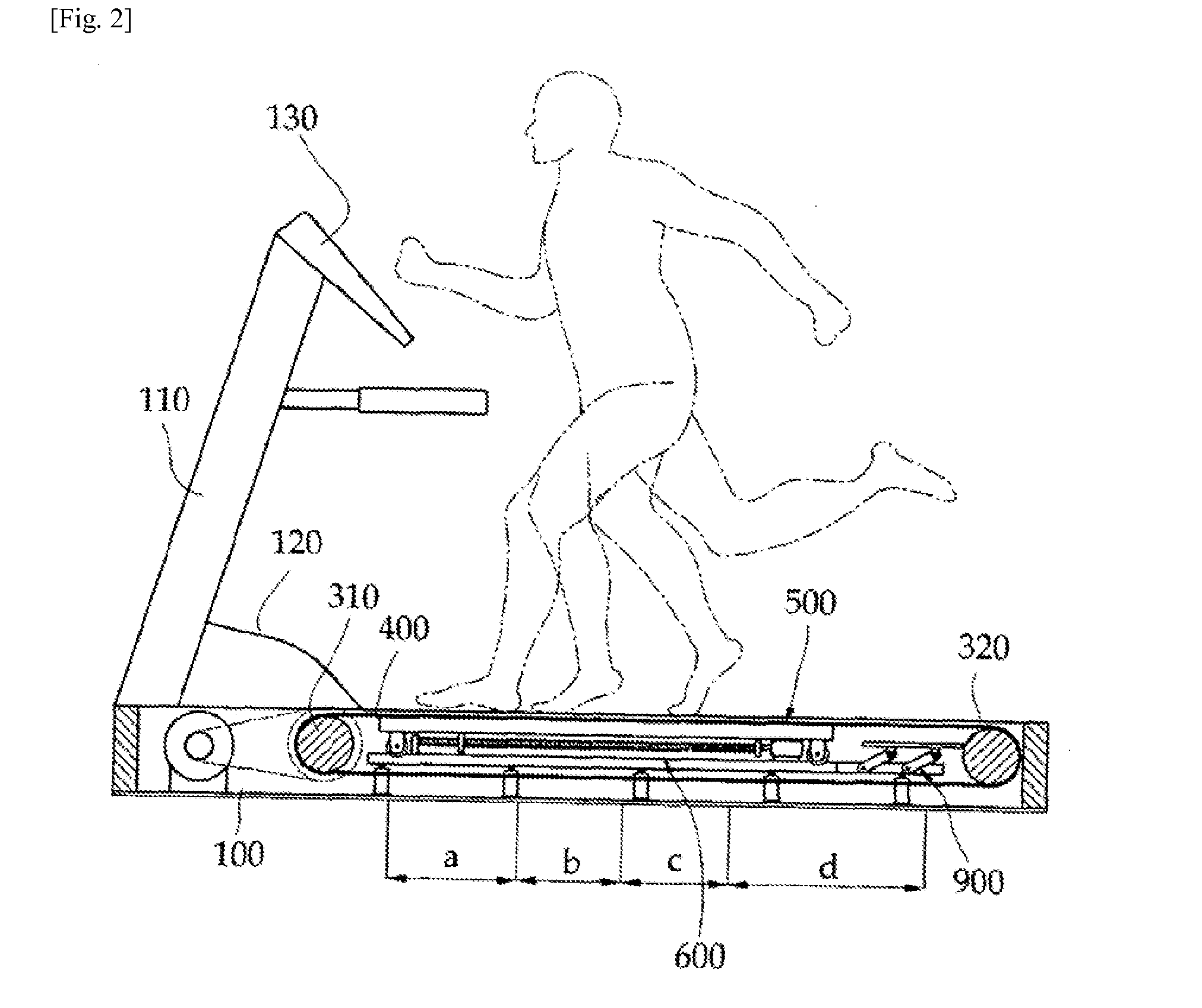
[0034]FIG. 2 is a view showing a treadmill according to an embodiment of the present invention, FIG. 3 is an exploded perspective view showing the treadmill according to the embodiment of the present invention, FIG. 4 is a side cross-sectional view showing a main frame d an auxiliary support frame according to the embodiment of the present invention, FIG. 5 is a perspective view showing a position recovering means according to the embodiment of the present invention, and FIG. 6 is a front cross-...


PUM


Abstract

Disclosed is a treadmill which comprises: a main frame; a treadmill belt which is installed inside said main frame, and rotates in connection with the rotation of a support roller through an operation of a driving unit; and a pair of left and right support decks which are placed in an inner space of said treadmill belt, and support said treadmill belt when pressure is applied to an upper surface of said treadmill belt from an upper side, wherein said support decks are installed to move along a guide rail installed in said main frame in connection with the rotation of said treadmill belt and running of a user.

Description

TECHNICAL FIELD [0001]The present invention relates to a treadmill, and more particularly, to a treadmill capable of minimizing frictional resistance between a running belt and a support deck during a walking or running operation to save driving energy for rotation of the running belt, and minimizing application of an excessive load to parts related to the rotation of the running belt to increase durability.BACKGROUND ART [0002]In general, treadmills in which a running belt is rotated by a power source, an exerciser runs or walks on the rotating running belt, and thus the exerciser can perform exercise are being developed in various types.[0003]An example of such a treadmill is disclosed in Korean Utility Model Registration No. 20-0261701 described below that is a patent document.[0004]A treadmill 1 of the related art s constituted by a driving roller 7 and a driven roller 9, each having both ends supported by a frame 10, disposed in parallel a constant distance from each other, and...

Claims


Application Information

Patent Timeline
Patent Type & Authority Applications(United States)
IPC IPC(8): A63B22/02
CPCA63B22/02A63B22/0242A63B22/0285A63B23/04A63B2071/065A63B23/00
Inventor LEE, BYUNG DON
Owner LEE BYUNG DON
Why Eureka
Try Eureka