Automatic tripping device for push-pull trolley for working roll changing

A technology of automatic decoupling and pushing and pulling of carts, which is applied in the fields of manufacturing tools, metal processing equipment, metal rolling, etc., can solve the equipment failure rate, difficulty in post-maintenance equipment costs, increased energy consumption, increased equipment structure complexity, and low automation. and other problems, to achieve the effect of saving driving energy, compact structure and simplified equipment structure

Inactive Publication Date: 2015-07-15
ANSTEEL HEAVY MACHINERY CO LTD
View PDF8 Cites 5 Cited by
  • Summary
  • Abstract
  • Description
  • Claims
  • Application Information

AI Technical Summary

Problems solved by technology

[0003] According to the needs of the roll changing process, the hook-in and disengagement of the push-pull coupler and the roll-changing coupler in the push-pull device must be carried out step by step according to the procedure. Generally, it is carried out in three ways. One is to manually hook in and out, that is, to hook in and out of the roll changing hook and the hook on the work roll system completely by manual operation. Although the structure of this method is simple, the disadvantage is that it must be manually operated. In the field operation, the degree of automation is very low; the second is semi-automatic hook-in and disengagement, that is, one of the two actions of hook-in or disengagement is completed by manual operation, and the other action is automatically completed by the equipment through a specific mechanism. The first type is slightly improved, but the disadvantage is that the structure is more complicated than the first type, and a special action drive device is required; the third is automatic hook-in and disengagement. This method uses a hydraulic cylinder or an electro-hydraulic push rod to complete the hook-in. This method has a high degree of automation and is now widely used. The disadvantage is that it is necessary to design more complicated mechanisms and mechanism actions to complete these two actions, and it must have additional special driving devices and consume energy to complete the work. This greatly increases the complexity of the equipment structure, and increases the equipment failure rate, difficulty of later maintenance, equipment cost and energy consumption.

Method used


Image

  • Automatic tripping device for push-pull trolley for working roll changing
  • Automatic tripping device for push-pull trolley for working roll changing
  • Automatic tripping device for push-pull trolley for working roll changing

Examples


Embodiment Construction

[0021] The present invention will be described in detail below in conjunction with the accompanying drawings, but it should be pointed out that the implementation of the present invention is not limited to the following embodiments.

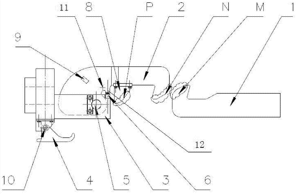
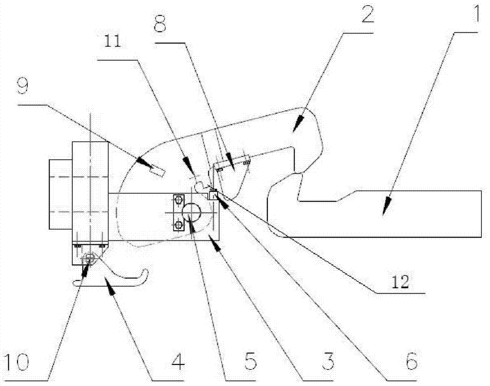
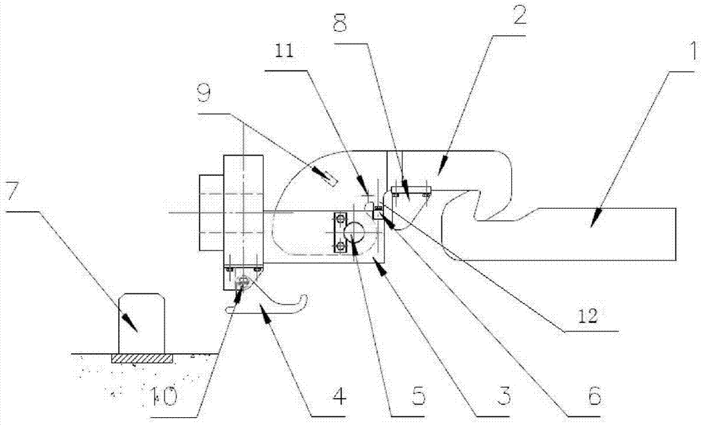
[0022] Such as Figure 1-7 As shown, an automatic uncoupling device for a work roll changing push-pull cart, comprising a roll-changing trolley coupler 1, a push-pull trolley coupler 2, a push-pull trolley frame 3, a push-pull trolley stop 7, the push-pull trolley coupler 2 and the push-pull trolley frame 3. Hinged connection. During work, the push-pull trolley and the roller changing trolley are connected with the push-pull trolley coupler 2 through the roller-changing trolley coupler 1, and the push-pull trolley stopper 7 is fixed on the ground or other relatively stationary objects with the push-pull trolley frame 3; The top surface M of the hook head of the small roller changing coupler 1 is a smooth curved slope, and the top surface N of the...


PUM


Abstract

The invention relates to an automatic tripping device for a push-pull trolley for working roll changing. The automatic tripping device comprises a roll changing trolley hook, a push-pull trolley hook, a push-pull trolley frame and a push-pull trolley check block, wherein the push-pull trolley hook is hinged to the push-pull trolley frame; during work, the push-pull trolley and a roll changing trolley are connected through the roll changing trolley hook and the push-pull trolley hook; the push-pull trolley check block is fixed on the ground, or other objects which are static relative to the push-pull trolley frame; a top surface M of a hook head of the roll changing trolley hook is a smooth inclined surface; a top surface N of a hook head of the push-pull trolley hook is a smooth inclined surface. The automatic tripping device disclosed by the invention is used for achieving a simple structure and a fully-automatic roll changing process in a roll changing process, overcoming the defects and shortcomings of the prior art and reducing the manpower and energy source consumption in a using process. The automatic tripping device disclosed by the invention is reasonable in design, compact in structure, simple and safe to operate, reliable to work, convenient to maintain, low in investment cost and energy-saving and dispenses with an external specific driving energy source.

Description

technical field [0001] The invention relates to a work roll change system of a rolling mill, in particular to an automatic decoupling device for a work roll change push-pull cart in the work roll change device of a rough rolling and finishing main rolling mill in a cold and hot rolling slab production line. Background technique [0002] At present, the automatic roll change device is used for the work roll change in the cold and hot rolling mills of rolling slabs at home and abroad. The roll change device is composed of two parts: a traverse device and a push-pull device. Move out and align the new roll system with the window of the frame; the push-pull device includes two parts: a roll changing cart and a push-pull cart, the roll changing cart is used to carry the roll system, and the push-pull cart is responsible for pushing in and pulling out the roll changing cart carrying the working roll system rack window. When the push-pull device is pushed into the work roll system...

Claims


Application Information

Patent Timeline
Patent Type & Authority Applications(China)
IPC IPC(8): B21B31/08
Inventor 李红高楠吴恩旭李宏伟金时赞鹿璐王艳儒张洪亮纪红
Owner ANSTEEL HEAVY MACHINERY CO LTD
Why Eureka
Try Eureka