Piezoelectric driven oscillating surface

a technology of oscillating surface and actuator, which is applied in the direction of mechanical equipment, air-flow influencers, transportation and packaging, etc., can solve the problems of less developed technology, requiring energy input, and rolling action of aircra

Active Publication Date: 2014-08-28
RENESSELAER POLYTECHNIC INST
View PDF4 Cites 4 Cited by
  • Summary
  • Abstract
  • Description
  • Claims
  • Application Information

AI Technical Summary

Benefits of technology

[0009]According to one aspect of the invention, an active roughness actuator is provided. The active roughness actuator includes a surface having at least one aperture; a compliant layer disposed on the surface such that the compliant layer covers the at least one aperture; a chamber having a fluid therein and a piezoelectric surface mechanically coupled to the chamber. The chamber is in fluid communication with the compliant layer via the at least one aperture. The piezoelectric surface is configured to displace the fluid in the chamber to control production of at least one dimple in the compliant layer proximate to the at least one aperture.
[0010]According to another aspect of the invention, a method of forming an active roughness actuator is provided. The method includes forming at least one aperture in a surface; disposing a compliant layer on the surface such that the compliant layer covers the at least one aperture; forming a chamber having a fluid therein such that the chamber is in fluid communication with the compliant layer via the at least one aperture; and mechanically coupling a piezoelectric surface to the chamber. The piezoelectric surface is configured to displace the fluid in the chamber to control production of at least one dimple in the compliant layer proximate to the at least one aperture.

Problems solved by technology

Active techniques may be more effective than passive techniques; however, they require energy input and are generally less developed as a technology.
For example, flow control may be desired during takeoff and landing of an aircraft, and may not be desired while the aircraft is cruising.
If one element is turned on while the other element is turned off, a non-symmetric lift is generated and may cause a roll action to the aircraft.
Although current dynamic roughness technologies can actively change the roughness, and can achieve high levels of roughness displacement, deficiencies do exist.
With compressed air, the frequency response is extremely low and cannot be used to excite the flow's natural frequencies.
Anything below this frequency will decay and not affect the flow field, which is undesirable.
Another drawback to current designs is that fluidic plumbing to the actuator is required.
This is a significant limitation of the technology and may not be desirable for use in an aircraft.
However, the mechanical aspects of the piston tends to be very complex.
Mechanically driven roughness elements may include an elaborate design and may be difficult to apply to a large scale surface.
The designs also tend to be heavy and may penalize an aircraft (by added fuel expenditure).
Also, a mechanical system may be limited to maximum frequencies that can be obtained (due to its structural design), and may have difficulty reaching the frequencies required to excite the flow field.
Although EAP technology does not have complex plumbing and may reach the frequencies of actuation required for flow excitement, the EAP has limited deflection capabilities.
Also, EAPs are limited to deflect downwards into the surface.
Lastly, a top surface of an EAP is electrified, which may require further development to make EAPs resilient to weather conditions, such as humidity and rain (which may cause outright failure of the actuator).

Method used


Image

  • Piezoelectric driven oscillating surface
  • Piezoelectric driven oscillating surface
  • Piezoelectric driven oscillating surface

Examples


example

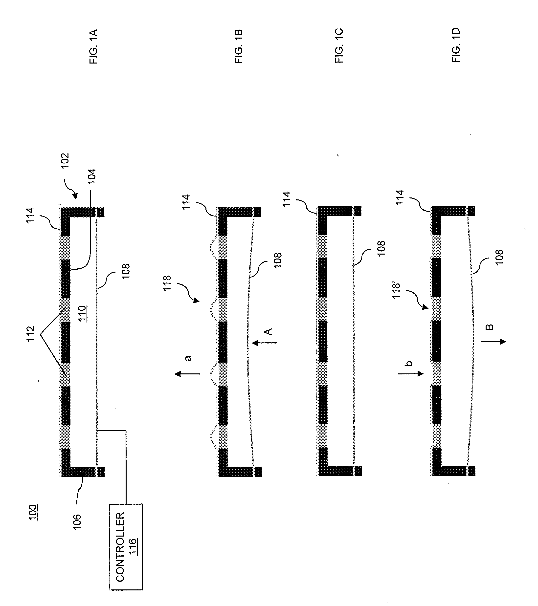
[0074]A feasibility experiment was conducted based on actuator 100 shown in FIG. 1A. Referring to FIG. 11, a cross-section diagram of exemplary PDOS active roughness actuator 1100 is shown. Similarly to actuator 100 (FIG. 1A), actuator 1100 includes piezoelectric surface 108 mechanically coupled to chamber 1102, surface 1104 having first apertures 1112 and compliant layer 1114. Chamber 1102 includes surface 1104 and side surfaces 1106. Chamber 1102 includes cavity 1110 having a fluid therein. Actuator 1100, in addition, includes plate 1116 having second apertures 1118. Second apertures 1118 are desirably aligned with first apertures 1112. In actuator 1100, compliant layer 1114 is disposed (and clamped) between surface 1104 and plate 1116. Piezoelectric surface 108, compliant layer 1114 and plate 1116 are mechanically coupled to chamber 1102 via fastening screws 1120. Thus, like actuator 100 (FIG. 1), actuator 1100 is a compact design, with piezoelectric surface 108 directly driving ...


PUM

PropertyMeasurementUnit
frequenciesaaaaaaaaaa
displacementsaaaaaaaaaa

Abstract

Disclosed herein is an active roughness actuator and a method of forming an active roughness actuator. The active roughness actuator includes a surface having at least one aperture; a compliant layer disposed on the surface such that the compliant layer covers the at least one aperture; a chamber having a fluid therein and a piezoelectric surface mechanically coupled to the chamber. The chamber is in fluid communication with the compliant layer via the at least one aperture. The piezoelectric surface is configured to displace the fluid in the chamber to control production of at least one dimple in the compliant layer proximate to the at least one aperture.

Description

CROSS REFERENCE TO RELATED APPLICATIONS[0001]This application is related to and claims the benefit of U.S. Provisional Application No. 61 / 761,756 entitled PIEZOELECTRIC DRIVEN OSCILLATING SURFACE filed on Feb. 7, 2013 and U.S. Provisional Application No. 61 / 733,460 entitled PIEZOELECTRIC DRIVEN OSCILLATING SURFACE filed on Dec. 5, 2012, the contents of each of which are incorporated herein by reference.FIELD OF THE INVENTION[0002]The present invention relates to the control of fluid through an active roughness actuator having a piezoelectric driven oscillating surface (PDOS).BACKGROUND OF THE INVENTION[0003]“Flow control” is the ability to control a fluid in a way that makes it behave differently than it would naturally. This is a field that has been steadily rising in aerodynamics and fluid dynamics. Flow control may be separated into two different techniques: passive techniques (i.e., always acting on the fluid) and active techniques (i.e., which may be turned on and off or propor...

Claims


Application Information

Patent Timeline
Patent Type & Authority Applications(United States)
IPC IPC(8): F15D1/00
CPCF15D1/007B64C21/10B64C23/005Y02T50/10Y10T29/42Y10T137/2213
Inventor VAN BUREN, TYLERAMITAY, MICHAEL
Owner RENESSELAER POLYTECHNIC INST
Why Eureka
Try Eureka