
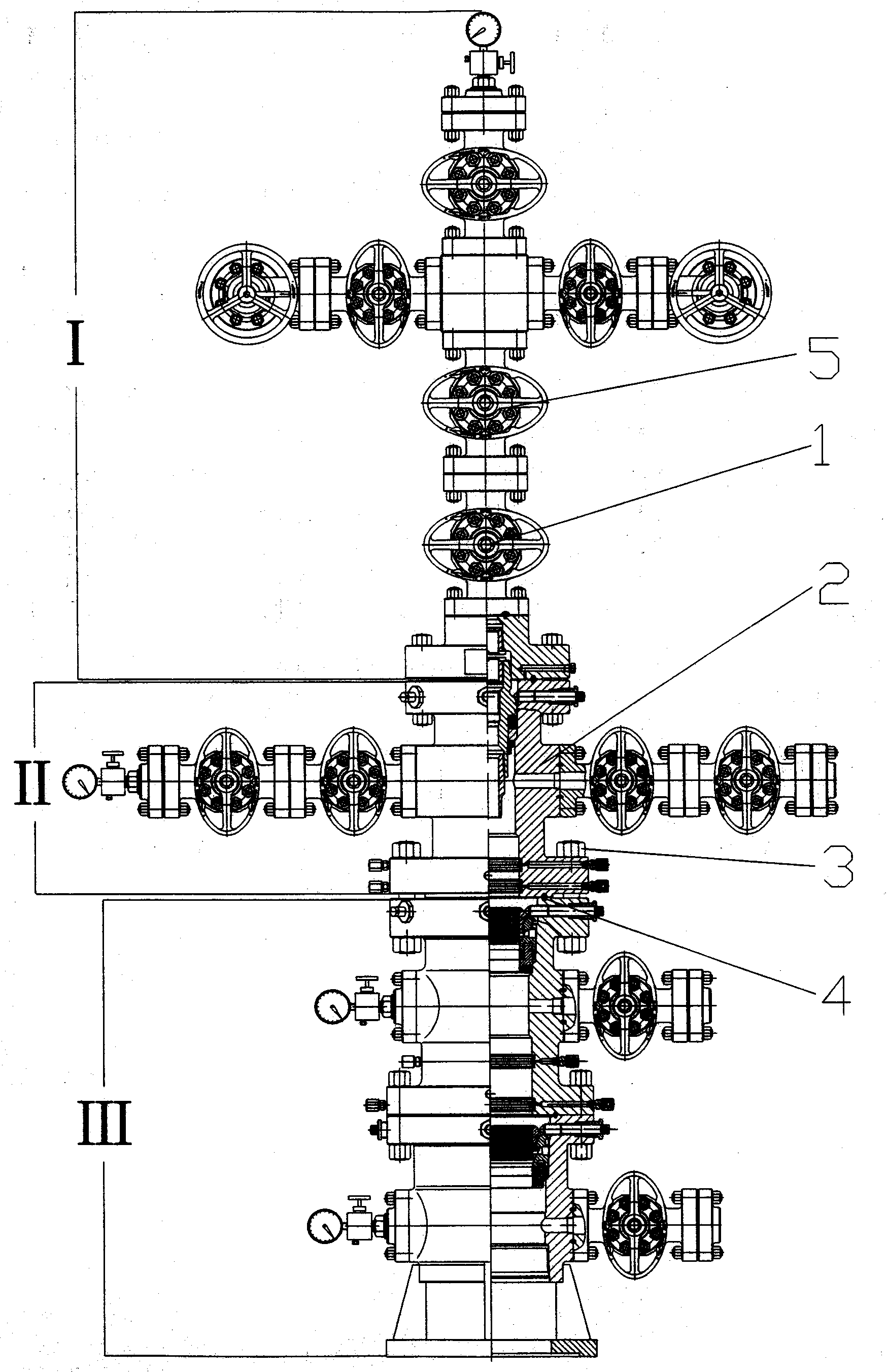
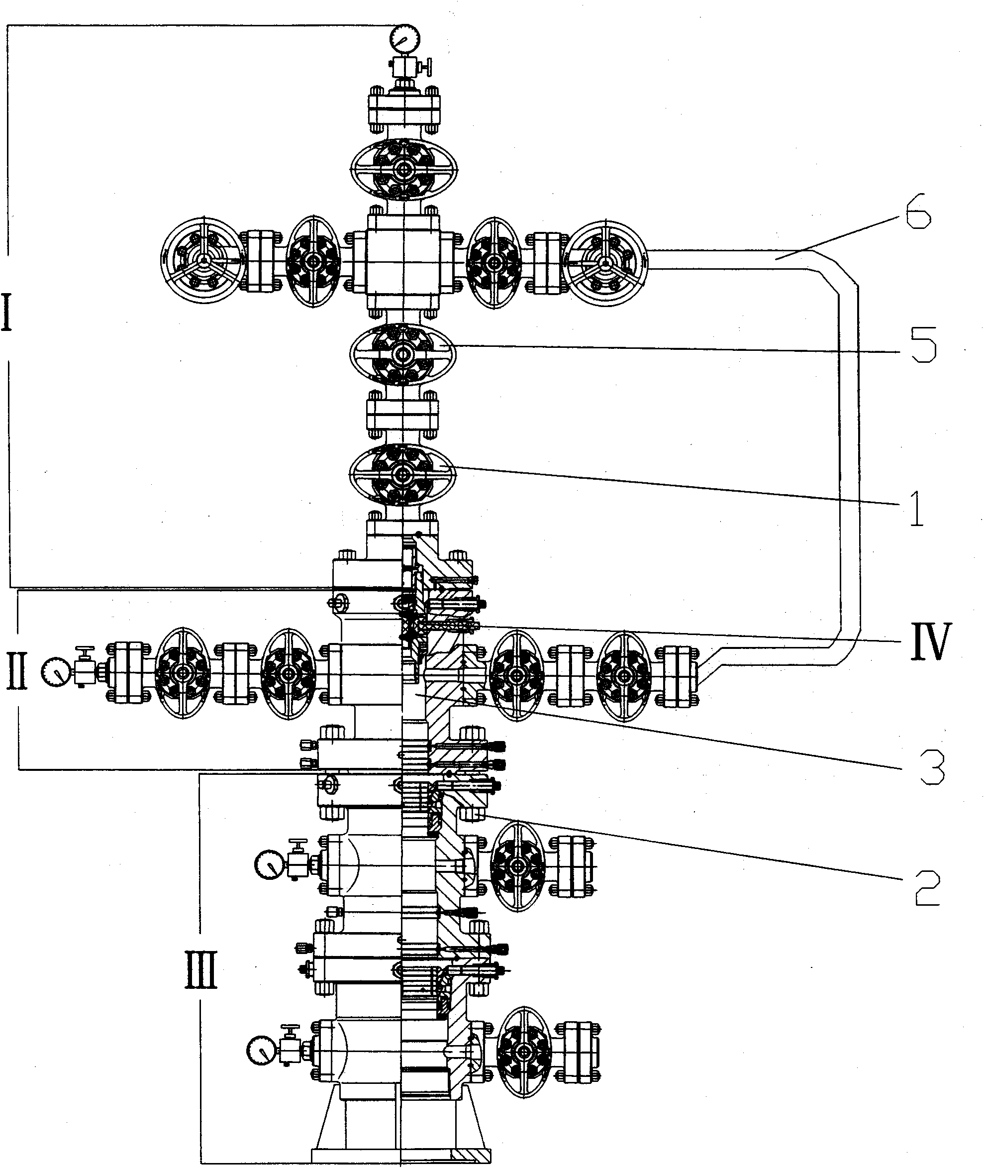
Sulfur-resistant oil and gas extraction wellhead device provided with structure for replacing No.1 main control valve

A technology of wellhead device and main control valve, which is applied in the direction of wellbore/well valve device, earthwork drilling and production, wellbore/well components, etc. It can solve problems such as costing a lot of manpower, polluting the environment, and damaging oil and gas production layers at the bottom of the well , to achieve the effect of scientific and reasonable design, simple overall structure and wide application range

Inactive Publication Date: 2010-12-15
黄振富
View PDF7 Cites 4 Cited by
  • Summary
  • Abstract
  • Description
  • Claims
  • Application Information

AI Technical Summary

Problems solved by technology

Once the thread inside the tubing hanger is corroded or washed out, the back pressure valve cannot be fixed. At this time, the only way to replace the No. 1 main control valve is to kill the well with heavy mud, which will cost a lot of manpower and financial resources
The cost ranges from millions to as many as several million yuan, and at the same time it will cause damage to the oil and gas production layer at the bottom of the well or pollute the environment

Method used


Image

  • Sulfur-resistant oil and gas extraction wellhead device provided with structure for replacing No.1 main control valve
  • Sulfur-resistant oil and gas extraction wellhead device provided with structure for replacing No.1 main control valve
  • Sulfur-resistant oil and gas extraction wellhead device provided with structure for replacing No.1 main control valve

Examples


Embodiment Construction

[0028] Combine below Figure 2 ~ Figure 3 , to further describe the specific implementation of the present invention in detail, it should be noted that: this embodiment is descriptive, not restrictive, and cannot be used to limit the protection scope of the present invention.

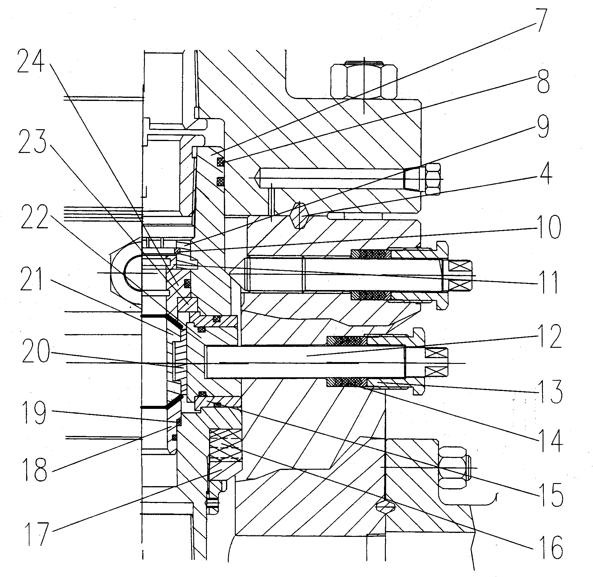
[0029] The present invention is a self-contained replacement of No. 1 main control gate valve 1 structure anti-sulfur oil and gas wellhead device, arranged on the tubing head II between the Christmas tree I and the casing head III, including the wellhead internal cutting device 9 and pressure balance device. In the tubing head II, the tubing hanger 7 is fixed inside the tubing head spool 3 through a jacking screw, a sealing ring 8 is arranged between the tubing hanger 7 and the inner wall of the tubing head spool 3, and a sealing ring 16 and Gasket 17 plays a more perfect sealing effect. The cutting device 9 inside the wellhead is arranged at the position of the tubing head cross body 3 below the No. ...


PUM


Abstract

The invention provides a sulfur-resistant oil and gas extraction wellhead device provided with a structure for replacing a No.1 main control valve. The device comprises a wellhead cut-off device and a pressure balancing device, wherein the wellhead cut-off device consisting of an operating rod and a movable sealing device is arranged on an oil gas well in an oil pipe hanger below the No.1 main control valve; the movable sealing device is arranged in the oil gas well in the oil pipe hanger and has a movable sealing surface corresponding to a flow passage cross section in an oil gas passage; one end of the operating rod is connected with a rotary sealing device while the other end passes through a wall of the oil pipe hanger and extends by a certain distance; and the pressure balancing device is a high-pressure gas passage of which one end is connected to the oil gas passage of a four-way casing valve of a tubing head below the No.1 main control valve while the other end is connected to the oil gas passage of a Christmas tree production valve above the No.1 main control valve. The device has the advantages of simple overall structure, accordance with the standard, scientific and reasonable design, convenient, rapid, safe and reliable use, no need of large-size special equipment and wide application range.

Description

technical field [0001] The invention belongs to an oil (gas) wellhead device. In particular, it is a self-contained replacement No. 1 main control valve structure anti-sulfur oil and gas wellhead device. Background technique [0002] There are various structures of oil and gas wellhead devices. According to various functions, it is roughly a double-wing wellhead device, a single-wing wellhead device, a double-tube wellhead device, and a single-tube wellhead device. All kinds of wellhead devices can play their own functions, and can control the pressure, production and fluid medium flow of crude oil and natural gas in oil and gas wells. Once the anti-sulfur production oil and gas wellhead device is installed on the production oil and gas well, the No. 1 main control valve on the oil and gas tree is the main gate valve for controlling the high-pressure oil and gas fluid in the well. It will directly control the oil and gas fluids from the formation, which is crucial for a p...

Claims


Application Information

Patent Timeline
IPC IPC(8): E21B33/03E21B34/02
Inventor 黄振富
Owner 黄振富
Learn More