Eureka AIR delivers breakthrough ideas for toughest innovation challenges, trusted by R&D personnel around the world.

Auxiliary equipment for use with drilling apparatus

Inactive Publication Date: 2014-08-28
GOUWS PETRUS CHRISTIAAN
View PDF2 Cites 2 Cited by
  • Summary
  • Abstract
  • Description
  • Claims
  • Application Information

AI Technical Summary

Benefits of technology

[0014]In a particular embodiment, the vanes may be in the form of panel elements. More specifically, the vanes may be in the form of flexible panel elements. Yet more specifically, the vanes may be in the form of rubber flaps.
[0015]The auxiliary support structure of the auxiliary working apparatus of the invention particularly may comprise a structure that can support the displacement means in its required operative configuration with respect to a drill pipe and a hole being drilled by the drill pipe, in use, of the drilling apparatus with which the auxiliary working apparatus is operatively used. Particularly for the support of the auxiliary support structure of the auxiliary working apparatus by the support structure of the associated drilling apparatus, the auxiliary working apparatus may include a set of elongate flexible elements which operatively support the auxiliary support structure in a suspended configuration from the support structure of the drilling apparatus. Such support can be conveniently provided for by a set of chains or cables, while

Problems solved by technology

As such, and without the platform being located as described, the chippings will blow directly onto the operating parts of the drilling apparatus referred to and this clearly will result in unnecessary wear and tear on these parts, as the chippings are very abrasive.
The continuous displacement of soil from a hole being drilled, as described, is important insofar as clogging of the annular space with chippings will otherwise result, thus causing resistance to the rotation of the drill pipe and unnecessary strain on the drill motor.
It has been found, however, that the chippings being “blown” from the annular space referred to, can also pass through the hole in the platform through which the drill pipe extends, thus potentially defeating the objective of the platform, which is to protect the operating parts of the drilling apparatus from the chippings.
Still further, chippings blown from the annular space will tend to gather on the ground immediately adjacent the hole being drilled and on the platform immediately adjacent the hole through which the drill pipe extends, this gathering of the chippings resulting in “piles” of chippings being formed that will collapse from time to time and result in the chippings dropping back into the annular space.
Clearly, for as long as air pressure is sufficient, these chippings will again be “blown” from the annular space, but particularly when air pressure is insufficient or becomes insufficient due to the depth of the hole being drilled, the chippings dropping back into

Method used


Image

  • Auxiliary equipment for use with drilling apparatus
  • Auxiliary equipment for use with drilling apparatus
  • Auxiliary equipment for use with drilling apparatus

Examples


Example

DETAILED DESCRIPTION OF THE DRAWINGS

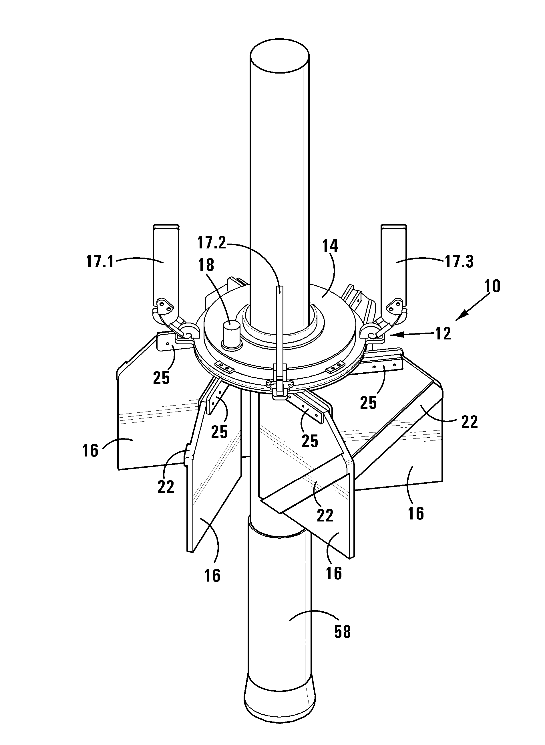
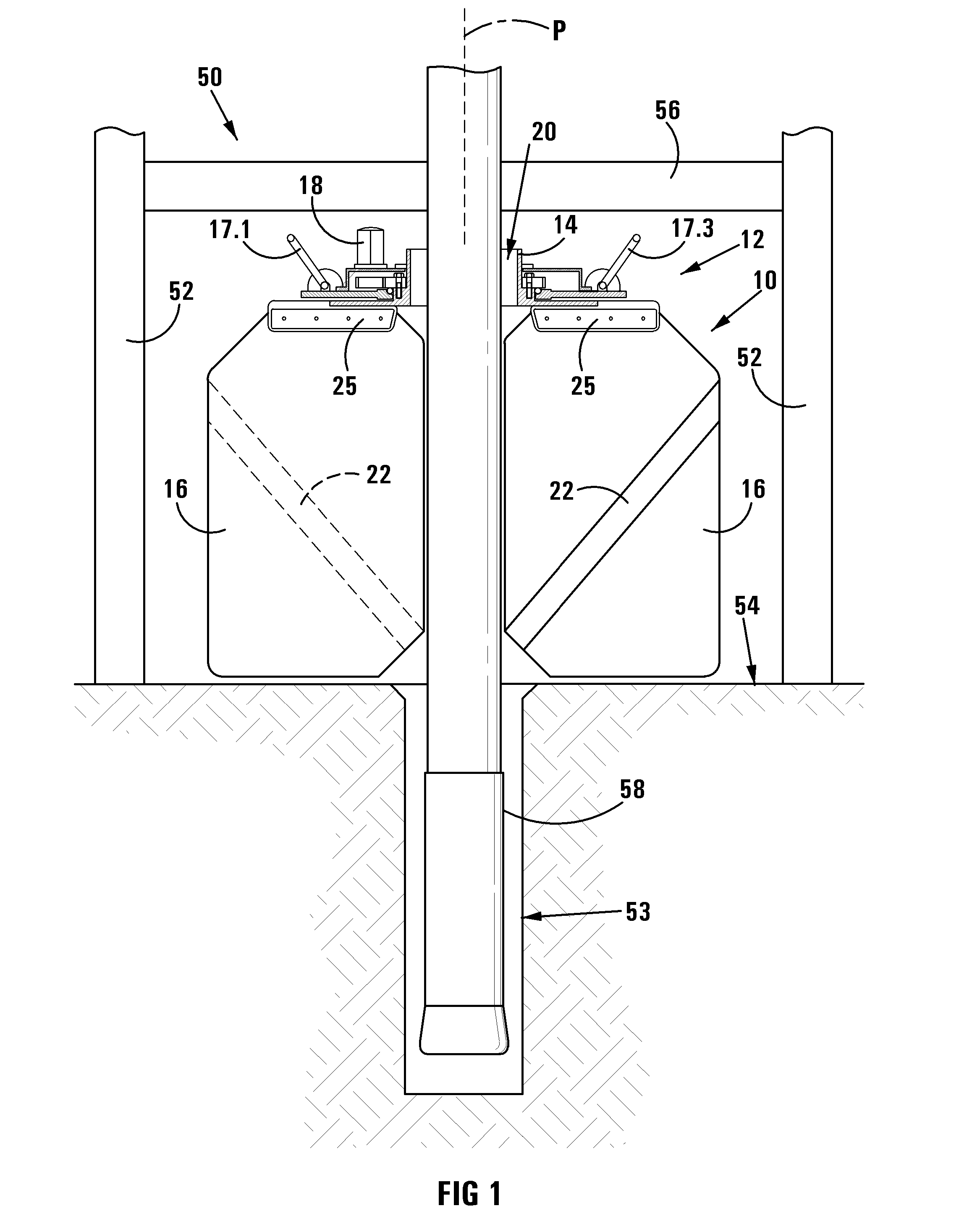
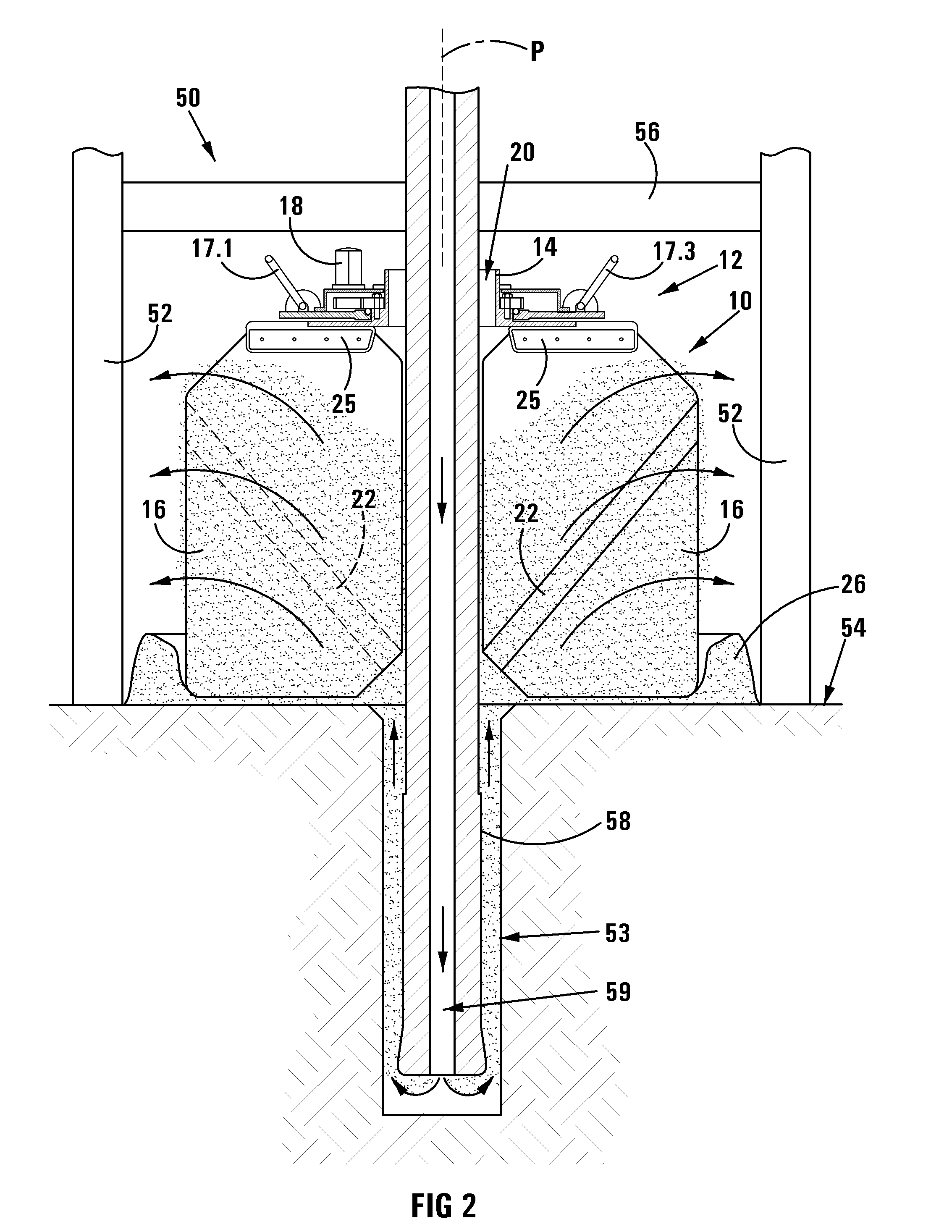
[0024]Referring to the drawings, an auxiliary working apparatus for use with a drilling apparatus for drilling holes into the ground, in accordance with the invention, is designated generally by the reference numeral 10. The auxiliary working apparatus 10 comprises, broadly, an auxiliary support structure 12 including a hub 14, a number of vanes 16 mounted to the hub and a hydraulic motor 18 for driving the hub.

[0025]The auxiliary working apparatus 10 is configured for use with a drilling apparatus designated by the reference numeral 50, for drilling holes into the ground. The drilling apparatus 50 generally includes a support structure comprising a number of upright support columns 52 which are located on a ground surface 54 and a platform 56 which is supported in a horizontal configuration by the support columns in an arrangement wherein the platform forms a barrier at a spaced location above the ground. The drilling apparatus further includes a...


PUM


Abstract

An auxiliary working apparatus configured for use with a drilling apparatus including a platform which is supported above ground and a drill pipe which extends through a hole in the platform to be displaced into the ground for drilling a hole in the ground. The drill pipe is of a type having a central passage along which pressurized air is blown. The apparatus is mounted to an underside of the platform by means of an auxiliary support structure which includes a hub, a number of vanes mounted to the hub and a hydraulic motor for driving the hub. The vanes are in the form of flexible rubber flaps which are circumferentially spaced and extend radially outwardly from the hub. The vanes revolve around the drill pipe so as to displace chippings which are blown from the hole during a drilling operation, outwardly away from the drill pipe to form an annular mound around and spaced from the hole.

Description

FIELD OF INVENTION[0001]This invention relates to auxiliary equipment for use with drilling apparatus.BACKGROUND TO INVENTION[0002]The auxiliary equipment as herein envisaged, hereinafter referred to specifically as an auxiliary working apparatus, is provided particularly for use with a drilling apparatus of the type that is used in mines, for drilling holes into the ground. Such a drilling apparatus generally includes a support structure, for the stable support of the apparatus in the region where drilling is required, a drill motor mounted on the support structure and a drill pipe formed of a number of drill pipe sections, that is operatively connected to an output of the drill motor for the rotation thereof. Such a drilling apparatus includes also a displacement mechanism for displacing the drill motor and particularly the drill pipe connected thereto along a longitudinal axis of the drill pipe, for drilling purposes, the drilling operation usually including the insertion of exte...

Claims


Application Information

Patent Timeline
IPC IPC(8): E21B21/015
CPCE21B21/015
Inventor GOUWS, PETRUS CHRISTIAAN
Owner GOUWS PETRUS CHRISTIAAN
Why Eureka
Eureka Blog
Learn More