
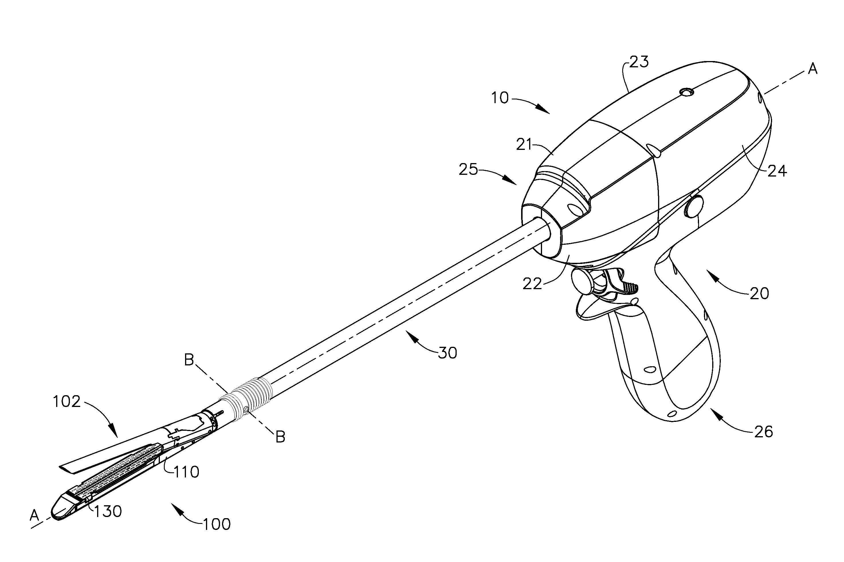
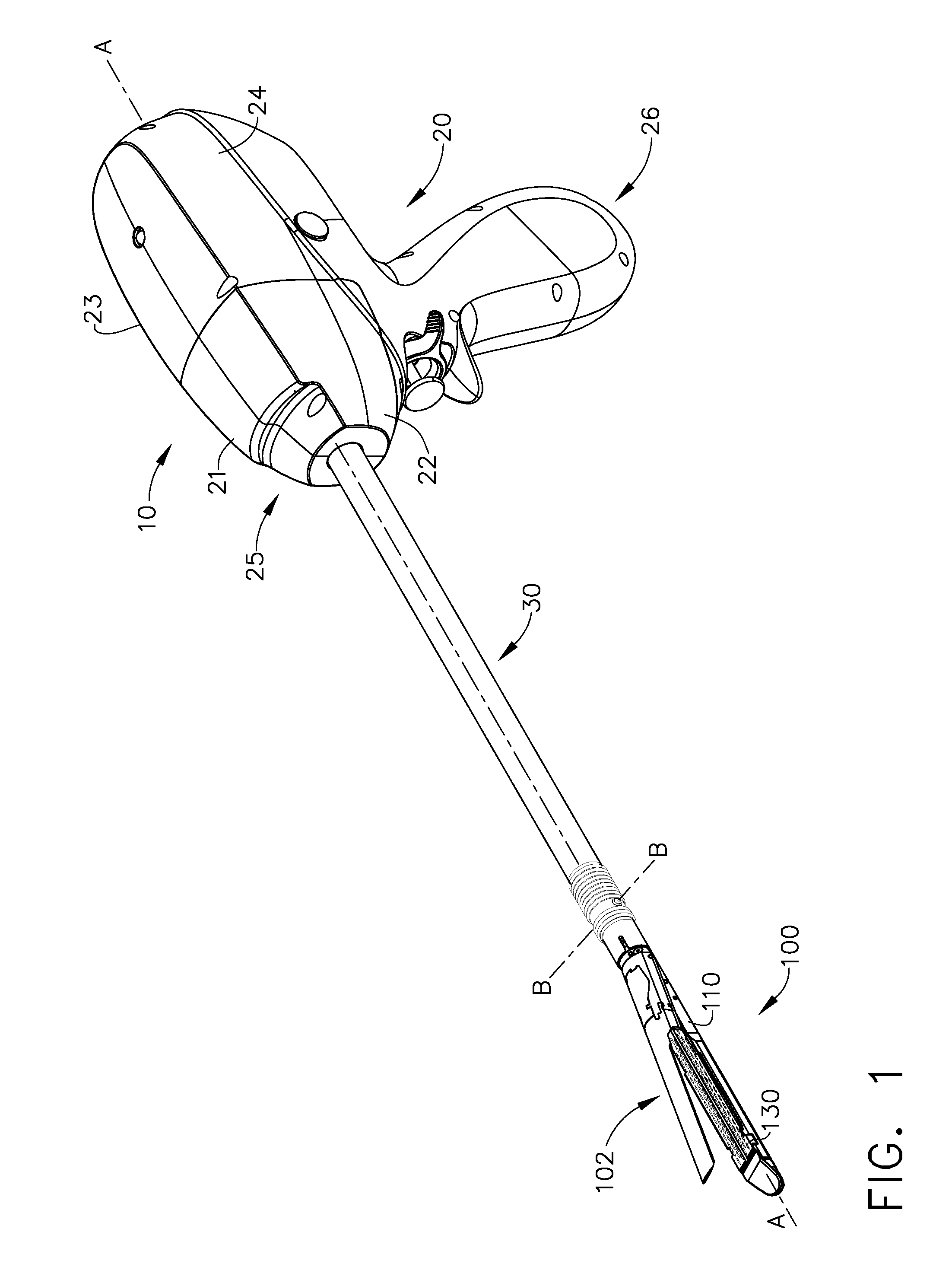
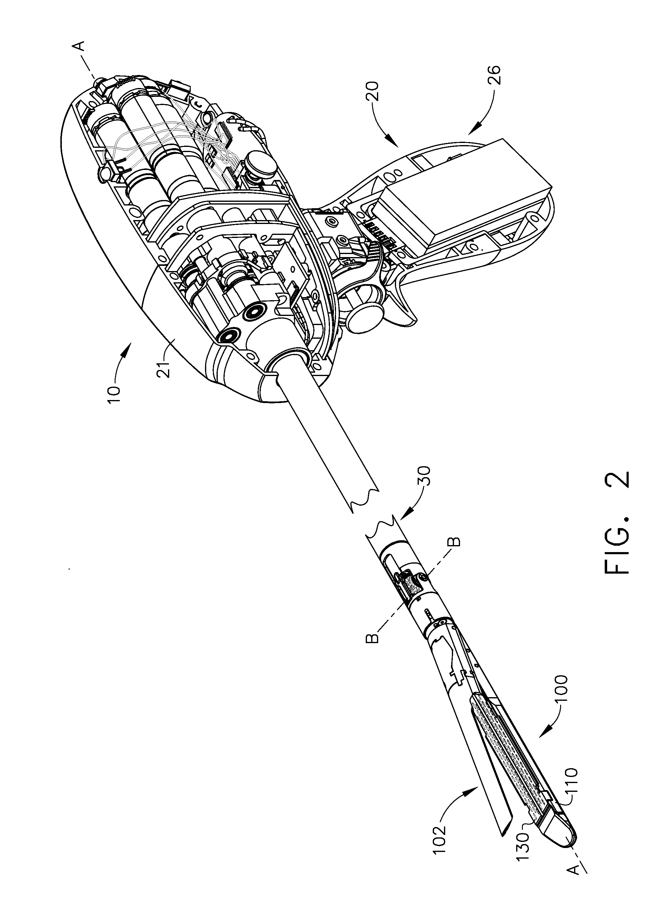
Sensor straightened end effector during removal through trocar

Active Publication Date: 2014-09-04
CILAG GMBH INTERNATIONAL
View PDF16 Cites 1464 Cited by
  • Summary
  • Abstract
  • Description
  • Claims
  • Application Information

AI Technical Summary

Benefits of technology

The present invention relates to surgical instruments and, in particular, to surgical staplers and staple cartridges designed to cut and staple tissue. The invention aims to improve the positioning and orientation of the end effector, or the part of the surgical instrument that comes into contact with the tissue, in relation to the elongate shaft assembly. The invention also includes various arrangements and configurations of the coupler assembly, which connects the end effector to the elongate shaft assembly. The technical effects of the invention include improved precision and accuracy in the positioning of the end effector, as well as more efficient and effective use of the surgical staplers and staple cartridges.

Problems solved by technology

If a surgeon is unsatisfied with the position of the end effector, however, the surgeon must typically activate a release mechanism on the surgical stapler to pivot the anvil into an open position and then reposition the end effector.

Method used


Image

  • Sensor straightened end effector during removal through trocar
  • Sensor straightened end effector during removal through trocar
  • Sensor straightened end effector during removal through trocar

Examples


Embodiment Construction

[0124]Applicant of the present application also owns the following patent applications that were filed on even date herewith and which are each herein incorporated by reference in their respective entireties:

[0125]U.S. patent application entitled “Rotary Powered Surgical Instruments With Multiple Degrees of Freedom”, Attorney Docket No. END7195USNP / 120287;

[0126]U.S. patent application entitled “Rotary Powered Articulation Joints For Surgical Instruments”, Attorney Docket No. END7188USNP / 120280;

[0127]U.S. patent application entitled “Articulatable Surgical Instruments With Conductive Pathways For Signal Communication”, Attorney Docket No. END7187USNP / 120279;

[0128]U.S. patent application entitled “Thumbwheel Switch Arrangements For Surgical Instruments”, Attorney Docket No. END7189USNP / 120281;

[0129]U.S. patent application entitled “Joystick Switch Assemblies For Surgical Instruments”, Attorney Docket No. END7192USNP / 120284;

[0130]U.S. patent application entitled “Electromechanical Surg...


PUM

PropertyMeasurementUnit
Angleaaaaaaaaaa
Accelerationaaaaaaaaaa
Distanceaaaaaaaaaa

Abstract

In various forms, a sensor-straightened end effector is disclosed. The sensor-straightened end effector may comprise an end effector coupled to a shaft at an articulation point. The end effector may be articulable at an angle with respect to the shaft. A sensor may be disposed on the sensor-straightened end effector, such as on the shaft or on the end effector. The sensor is configured to detect a gross proximal movement. When detecting a gross proximal movement, the sensor may generate a signal to control a motor to begin a straightening process to straighten the end effector with respect to the shaft.

Description

FIELD OF THE INVENTION[0001]The present invention relates to surgical instruments and, in various arrangements, to surgical cutting and stapling instruments and staple cartridges therefor that are designed to cut and staple tissue.BACKGROUND[0002]Surgical staplers are often used to deploy staples into soft tissue to reduce or eliminate bleeding from the soft tissue, especially as the tissue is being transected, for example. Surgical staplers, such as an endocutter, for example, can comprise an end effector which can be moved, or articulated, with respect to an elongate shaft assembly. End effectors are often configured to secure soft tissue between first and second jaw members where the first jaw member often includes a staple cartridge which is configured to removably store staples therein and the second jaw member often includes an anvil. Such surgical staplers can include a closing system for pivoting the anvil relative to the staple cartridge.[0003]Surgical staplers, as outlined...

Claims


Application Information

Patent Timeline
IPC IPC(8): A61B17/068
CPCA61B17/068A61B17/07207A61B17/320068A61B17/320092A61B18/1445A61B2017/00314A61B2017/00327A61B2017/00367A61B2017/00398A61B2017/00393A61B2017/00464A61B2017/0046A61B2017/00473A61B2017/00477A61B2017/00482A61B2017/00734A61B2017/2943A61B2017/2903A61B2017/2929A61B2017/2927A61B2017/2923A61B2017/2925A61B17/2202A61B17/1155A61B17/072G05G9/04796G05G2009/04777A61B2017/00017A61B18/085A61B2017/00022A61B2017/00026A61B2017/00039A61B2017/00075A61B2017/00115A61B2017/00123A61B2017/00128A61B2017/00199A61B2017/00221A61B2017/00323A61B2017/0069A61B2017/07271A61B2017/07278A61B2018/00607A61B2018/00619A61B2018/00791A61B2018/00875A61B2018/1455A61B2034/742A61B2090/033A61B2090/064A61B34/30A61B90/90A61B90/98A61B2090/0811A61B34/74A61B2090/061A61B2090/034A61B2090/065A61B2017/320089A61B2017/320071A61B2017/320094A61B2017/320093A61B2017/320097A61B2017/320095A61B2017/320069Y02A90/10A61B17/32002
Inventor BABER, DANIEL L.LEIMBACH, RICHARD L.ALBRECHT, THOMAS E.
Owner CILAG GMBH INTERNATIONAL
Learn More