Integrated portable stand, power supply, and control panel
Inactive Publication Date: 2014-09-04
AIR SYST
View PDF1 Cites 5 Cited by
Summary
Abstract
Description
Claims
Application Information
AI Technical Summary
This helps you quickly interpret patents by identifying the three key elements:
Problems solved by technology
Method used
Benefits of technology
[0010]It is, therefore, an object of the present invention to provide a stand including a main housing having a power supply cavity and a control cavity in which a power supply and controller are respectively housed. The main housing also includes access ports for external connection with the power supply. The stand also includes a leg assembly attached to a first side wall of the main housing, the leg assembly allowing for outward extension of a first leg and a second leg to increase the stability of the stand. The stand further includes a telescoping mast attached to the main housing. The te
Problems solved by technology
However, if there are multiple parts that need to be connected in the dark in order to set up a platform, work is delayed, injuries may occur and parts may be lost and/or not available at all.
Even if there is light, a stand that is not self-contained and that requires connections of parts to erect for use may cause delays in the st
Method used
Image
Click on the blue label to locate the original text in one second.
Reading with bidirectional positioning of images and text.
Examples
Example
[0040]The detailed embodiments of the present invention are disclosed herein. It should be understood, however, that the disclosed embodiments are merely exemplary of the invention, which may be embodied in various forms. Therefore, the details disclosed herein are not to be interpreted as limiting, but merely as a basis for teaching one skilled in the art how to make and / or use the invention.
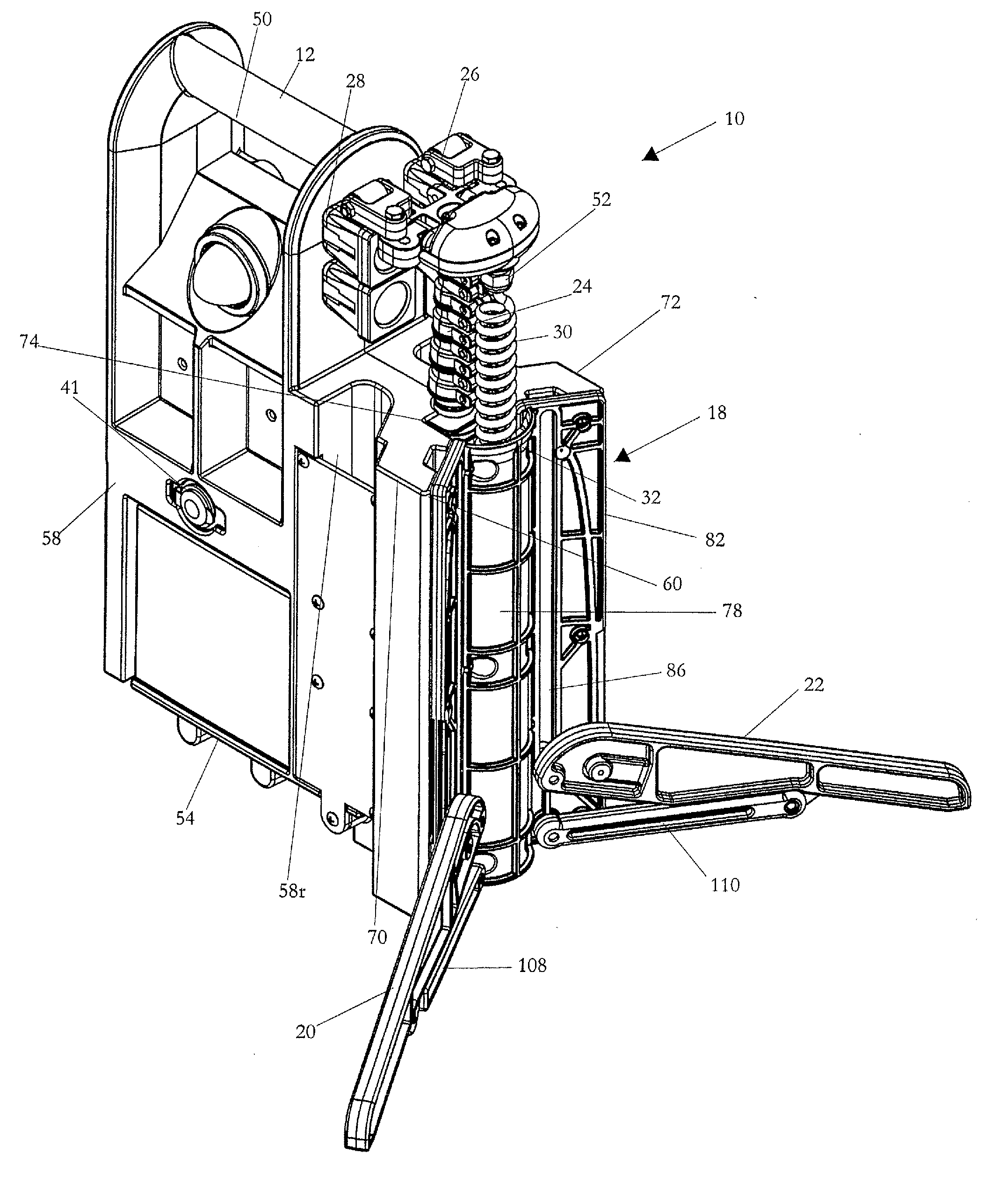
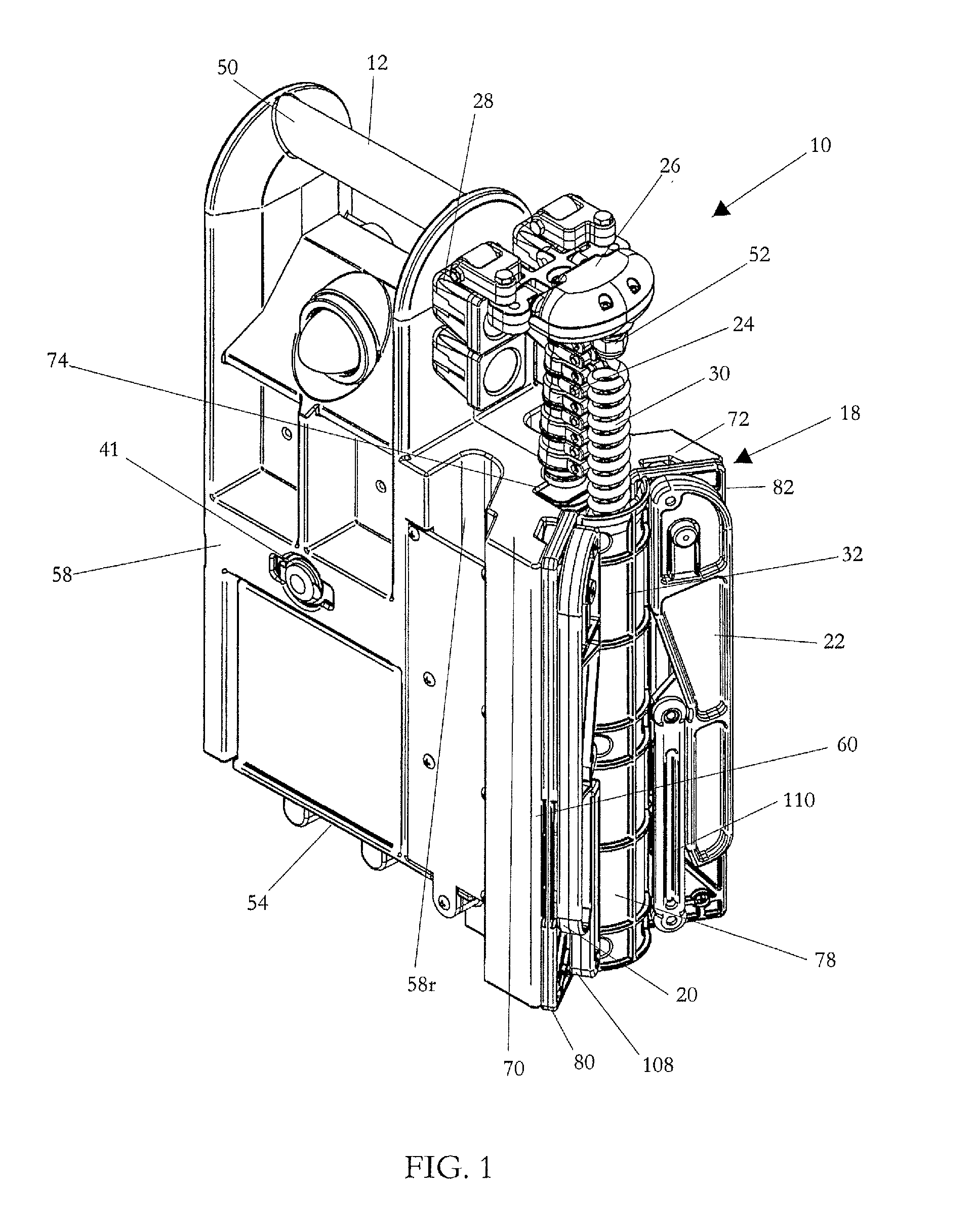
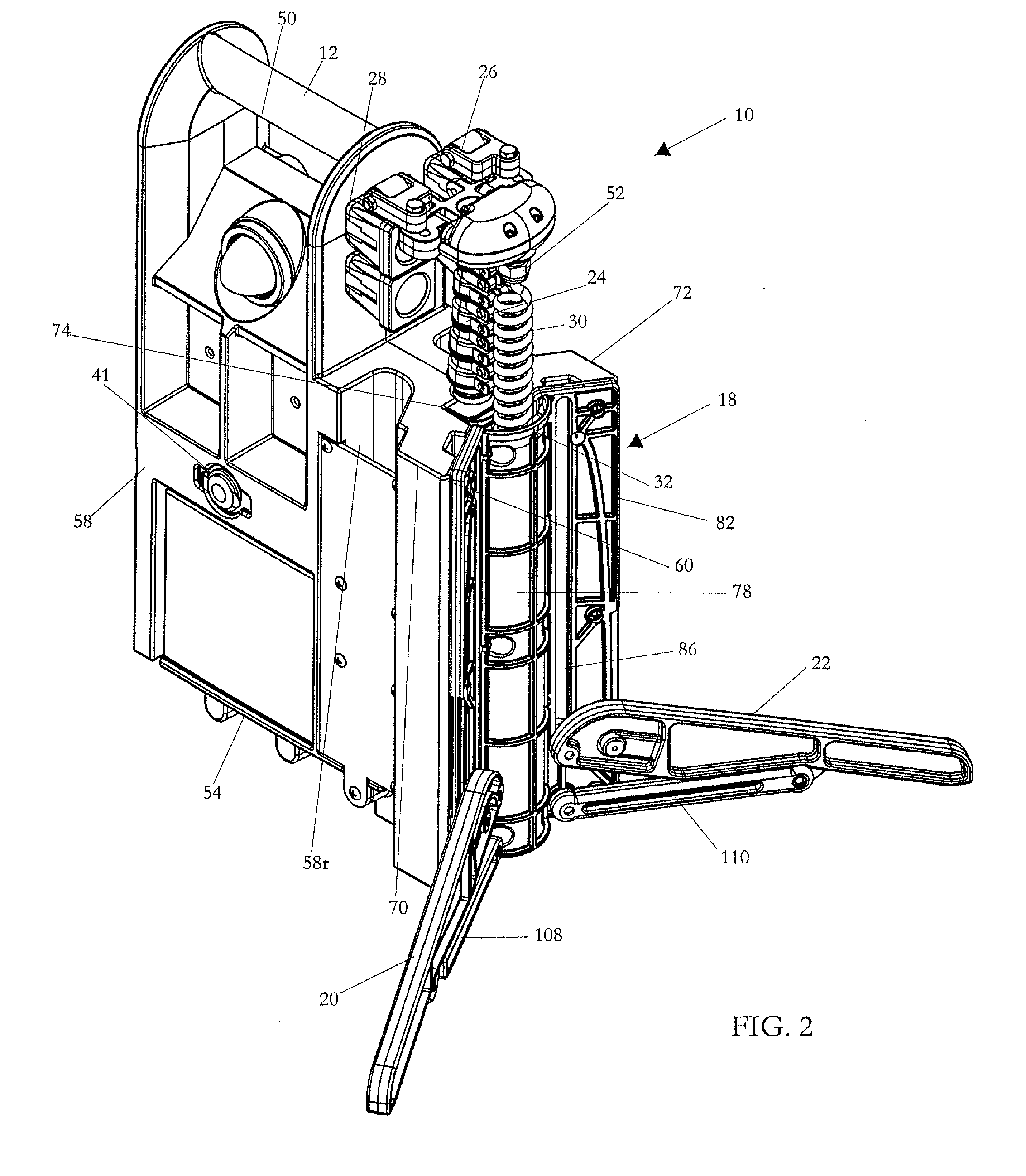
[0041]With reference to the various figures, a stand 10 in accordance with the present invention is disclosed. The stand 10 includes a main housing 12 for holding a power supply 14 and a controller 16. A leg assembly 18 is attached to one end of the main housing 12. The leg assembly 18 allows for outward extension of a pair of opposed legs 20, 22 to increase the stability of the stand 10.
[0042]In addition, and as will be explained below in greater detail, the stand 10 includes a telescoping mast 24 attached to the main housing 12. The telescoping mast 24 includes a mount 26 for the selective at...
PUM
Abstract
A stand includes a main housing having a power supply cavity and a control cavity in which a power supply and controller are respectively housed. The main housing also includes access ports for external connection with the power supply. The stand also includes a leg assembly attached to a first side wall of the main housing, the leg assembly allowing for outward extension of a first leg and a second leg to increase the stability of the stand. The stand further includes a telescoping mast attached to the main housing. The telescoping mast includes a mount for the selective attachment of a functional device thereto. A power and control conduit connects the power supply and mount for the transmission of electric power and control signals to the functional device.
Description
CROSS REFERENCE TO RELATED APPLICATIONS[0001]This application is a continuation-in-part of U.S. Design patent application Ser. No. 29 / 469,816, entitled “HOUSING FOR A POWER SUPPLY AND CONTROLLER,” filed Oct. 15, 2013, and this application is continuation-in-part of 13 / 376,156, entitled “INTEGRATED PORTABLE STAND, POWER SUPPLY, AND CONTROL PANEL,” filed Mar. 23, 2012, which is currently pending, which is a national phase filing under 35 USC 371 of PCT / US10 / 37342, entitled “INTEGRATED PORTABLE STAND, POWER SUPPLY, AND CONTROL PANEL,” filed Jun. 3, 2010, which claims the benefit of U.S. Provisional Patent Application Ser. No. 61 / 183,950, entitled “INTEGRATED PORTABLE STAND, POWER SUPPLY, AND CONTROL PANEL,” filed Jun. 3, 2009.BACKGROUND OF THE INVENTION[0002]1. Field of the Invention[0003]The present invention relates to stands for supporting items in an elevated position with respect to the surroundings. More specifically, the invention relates to stands that are portable, easy to set...
Claims
Application Information
Patent Timeline
Application Date:The date an application was filed.
Publication Date:The date a patent or application was officially published.
First Publication Date:The earliest publication date of a patent with the same application number.
Issue Date:Publication date of the patent grant document.
PCT Entry Date:The Entry date of PCT National Phase.
Estimated Expiry Date:The statutory expiry date of a patent right according to the Patent Law, and it is the longest term of protection that the patent right can achieve without the termination of the patent right due to other reasons(Term extension factor has been taken into account ).
Invalid Date:Actual expiry date is based on effective date or publication date of legal transaction data of invalid patent.