
Display panel driving method, display apparatus, display panel driving apparatus and electronic apparatus

a technology of display panel and driving method, which is applied in the direction of electric digital data processing, instruments, computing, etc., can solve the problems of restricting the variation range of peak luminance level, and achieve the effect of reducing the variation range of peak luminance level

Active Publication Date: 2014-09-04
JOLED INC
View PDF12 Cites 1 Cited by
  • Summary
  • Abstract
  • Description
  • Claims
  • Application Information

AI Technical Summary

Benefits of technology

[0060]Therefore, it is demanded to provide a driving technique for a display panel wherein the peak luminance level can be adjusted over a wide range while both of motion artifact and flickering can be suppressed.
[0063]Consequently, a difference in luminance can be provided clearly between an image visually observed principally and any other image. As a result, a multiple overlapping phenomenon of images of a substantially equal luminance which makes a cause of motion artifact can be reduced. Consequently, even where the peak luminance level is to be adjusted over a wide range, deterioration of the picture quality can be suppressed.

Problems solved by technology

However, the restriction to the setting range leads to restriction of the variation range of the peak luminance level.

Method used


Image

  • Display panel driving method, display apparatus, display panel driving apparatus and electronic apparatus
  • Display panel driving method, display apparatus, display panel driving apparatus and electronic apparatus
  • Display panel driving method, display apparatus, display panel driving apparatus and electronic apparatus

Examples


Embodiment Construction

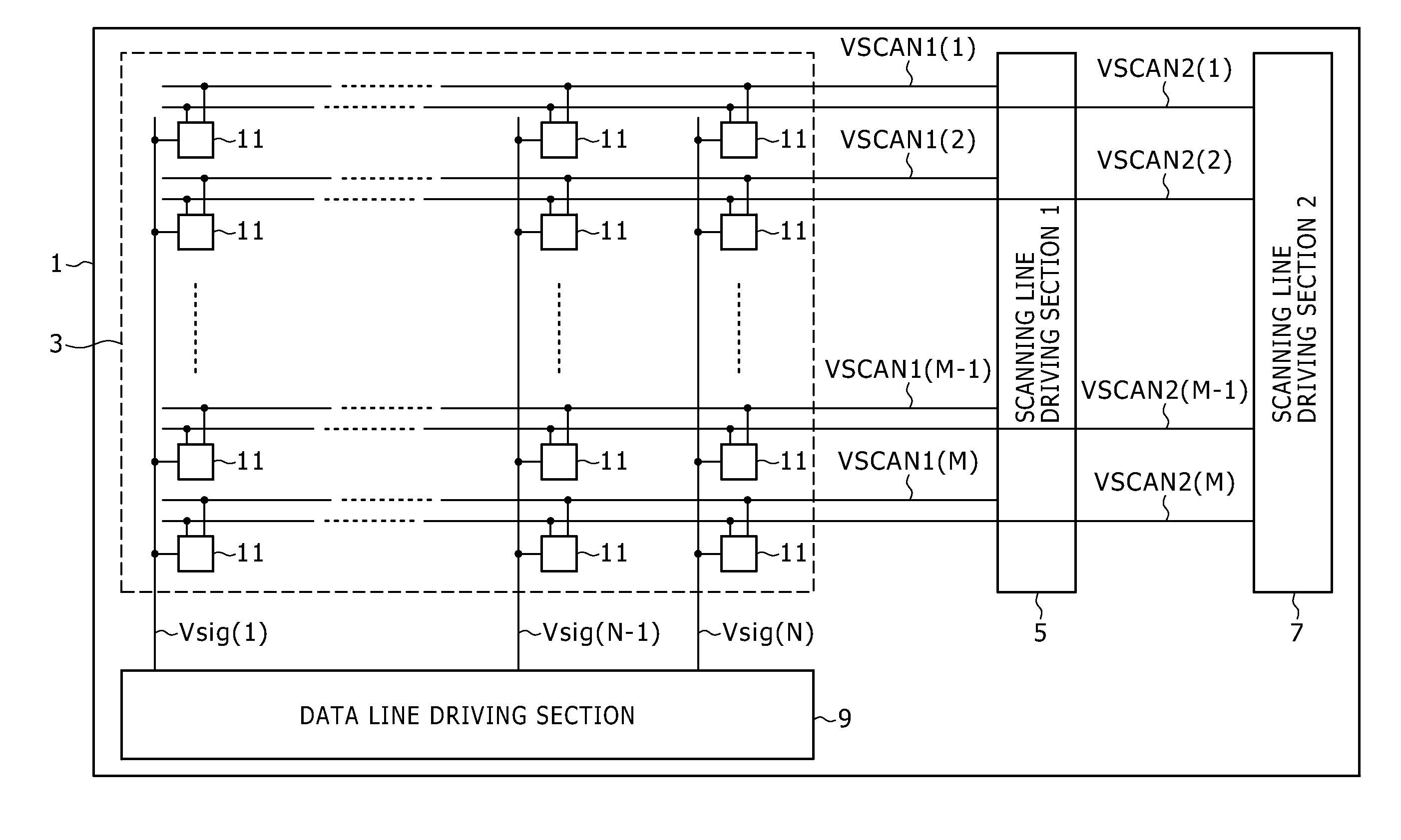
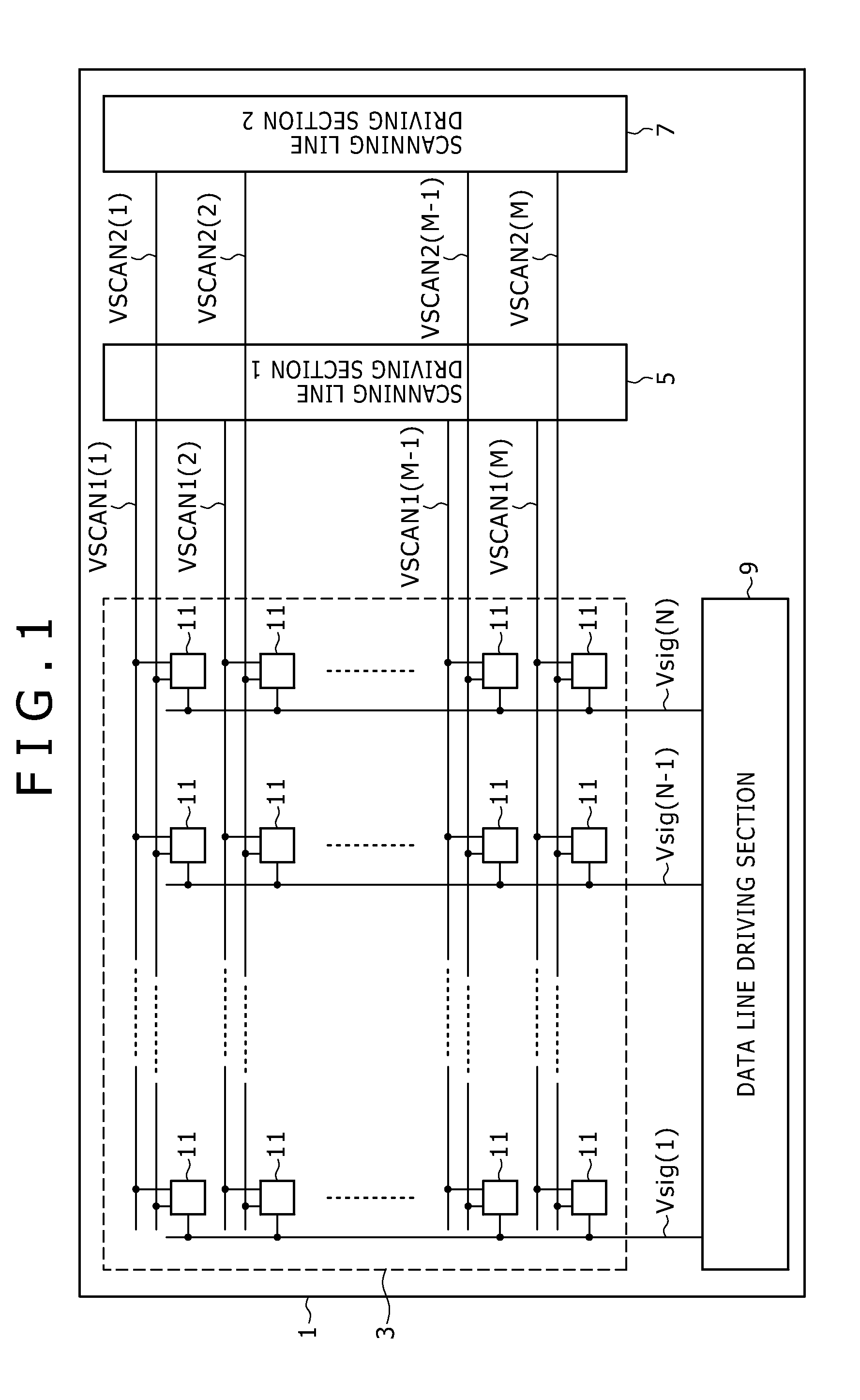
[0088]In the following, an organic EL panel of the active matrix driving type to which embodiments according to the present invention are applied is described.

[0089]It is to be noted that, to those matters which are not disclosed in the present specification and the accompanying drawings, techniques which are known in the technical field to which an embodiment according to the present invention belongs are applied.

A. Structure of the Organic EL Panel

[0090]FIG. 17 shows an example of a general configuration of an organic EL panel to which an embodiment according to the present invention is applied.

[0091]Referring to FIG. 17, the organic EL panel 21 includes a pixel array section 3, a first scanning line driving section 5 for writing a signal voltage, a second scanning line driving section 7 for controlling the light emitting period, a data line driving section 9, and a light emitting timing determination section 23. The pixel array section 3 includes pixel circuits 11 arranged in M r...


PUM


Abstract

In the present invention, there is provided a display panel driving method of the type wherein the total light emitting period length within a one-field period is controlled to variably control the peak luminance level of a display panel, the driving method including a step of variably controlling, where the one-field period has N light emitting periods disposed therein, N being equal to or greater than 2, the light emitting period length of a particular one of the light emitting periods and the other light emitting period or periods to provide a difference in luminance between the particular light emitting period and the other light emitting period or periods so that the particular light emitting period is visually observed as the center of light emission.

Description

CROSS REFERENCES TO RELATED APPLICATIONS[0001]This is a Continuation Application of U.S. patent application Ser. No. 12 / 153,477, filed May 20, 2008, which in turn claims priority from Japanese Patent Application No.: 2007-148699 filed in the Japan Patent Office on Jun. 5, 2007, the entire contents of which being incorporated herein by reference.BACKGROUND OF THE INVENTION[0002]1. Field of the Invention[0003]This invention relates generally to a method for controlling the peak luminance level of a display panel, and more specifically to a display panel driving method, a display apparatus, a display panel driving apparatus and an electronic apparatus.[0004]2. Description of the Related Art[0005]In recent years, development of display apparatus of the self-luminous type wherein organic EL (Electro Luminescence) devices are arranged in a matrix has been and is advancing. A display panel which uses an organic EL device is simple and easy in reduction in weight and film thickness and besi...

Claims


Application Information

Patent Timeline
Patent Type & Authority Applications(United States)
IPC IPC(8): G09G3/32
CPCG09G3/3225G09G2310/08G09G2320/0247G09G2320/0261G09G3/2022G09G3/3233H10K59/12G09G2300/08
Inventor ASANO, MITSURU
Owner JOLED INC
Learn More