
Cable connector assembly

a technology of cable connectors and connector assemblies, applied in the direction of electrical equipment, connection, coupling device connection, etc., can solve the problems of poor grounding, high cost, complex configuration of shielding shells, etc., and achieve the effect of reducing tensile stress, simple configuration, and low cos

Inactive Publication Date: 2014-09-04
MOLEX INC
View PDF6 Cites 0 Cited by
  • Summary
  • Abstract
  • Description
  • Claims
  • Application Information

AI Technical Summary

Benefits of technology

The present patent provides a cable connector assembly with a simple configuration and low cost that can better relieve tensile stress. The assembly comprises an electrical connector and a cable, which are connected together. The cable has wires and a cable filler, and the conductive terminals and wires are electrically connected. The assembly also has an inner mold and casing that surrounds the connection points and helps relieve stress by embedding the cable filler. The technology makes it more efficient and effective to connect cables, and it reduces the risk of failure.

Problems solved by technology

The existing cable connector is provided with the clamp device at the rear end of the shielding shell to clamp the cable fillers and the cable so as to attain an effect of stress relief, but a configuration of the shielding shell, formed by stamping a metal material, is complex and has a high cost.
In another aspect, during the process of folding back the cable fillers and the metal braided layer of such the cable connector, the cable fillers are easily to cover the metal braided layer, meaning that the metal braided layer can not establish an electrical connection with the clamp device, thereby resulting a poor grounding.

Method used


Image

  • Cable connector assembly
  • Cable connector assembly
  • Cable connector assembly

Examples


Embodiment Construction

[0017]While the Present Disclosure may be susceptible to embodiment in different forms, there is shown in the Figures, and will be described herein in detail, specific embodiments, with the understanding that the Present Disclosure is to be considered an exemplification of the principles of the Present Disclosure, and is not intended to limit the Present Disclosure to that as illustrated.

[0018]In the embodiments illustrated in the Figures, representations of directions such as up, down, left, right, front, rear and the like, used for explaining the structure and movement of the various elements of the Present Disclosure, are not absolute, but relative. These representations are appropriate when the elements are in the position shown in the Figures. If the description of the position of the elements changes, however, it is assumed that these representations are to be changed accordingly.

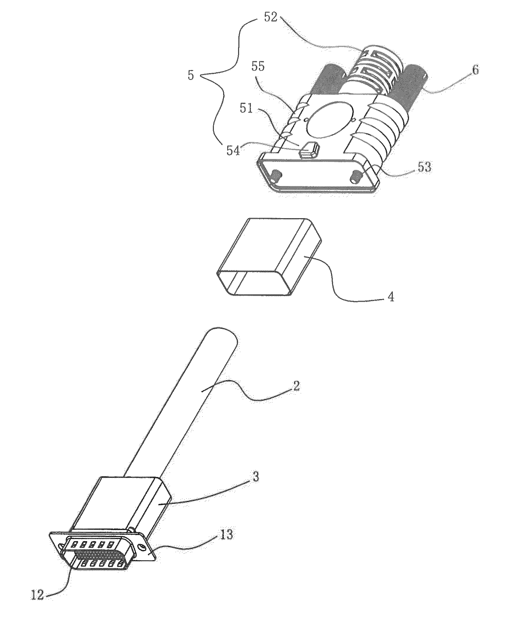
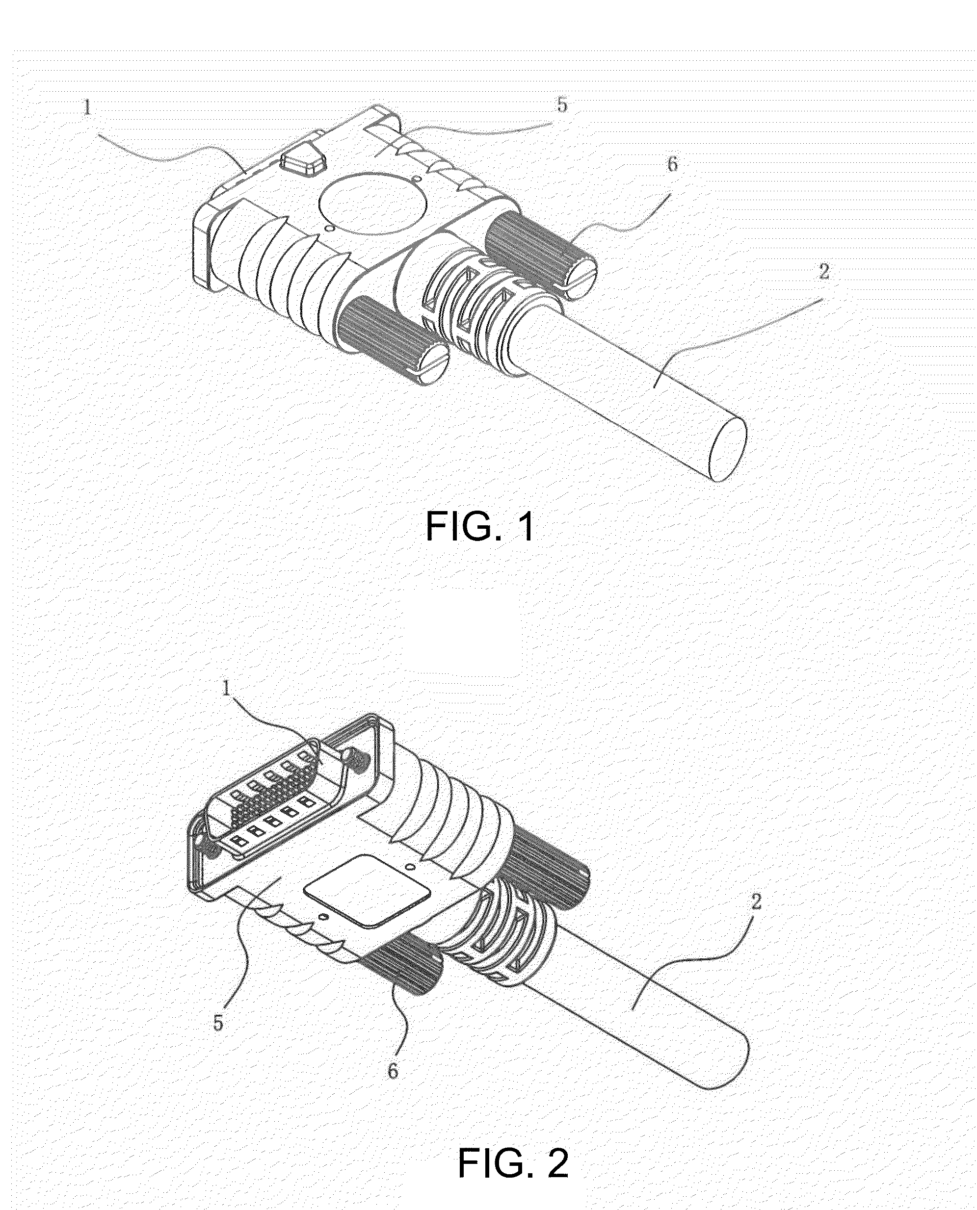
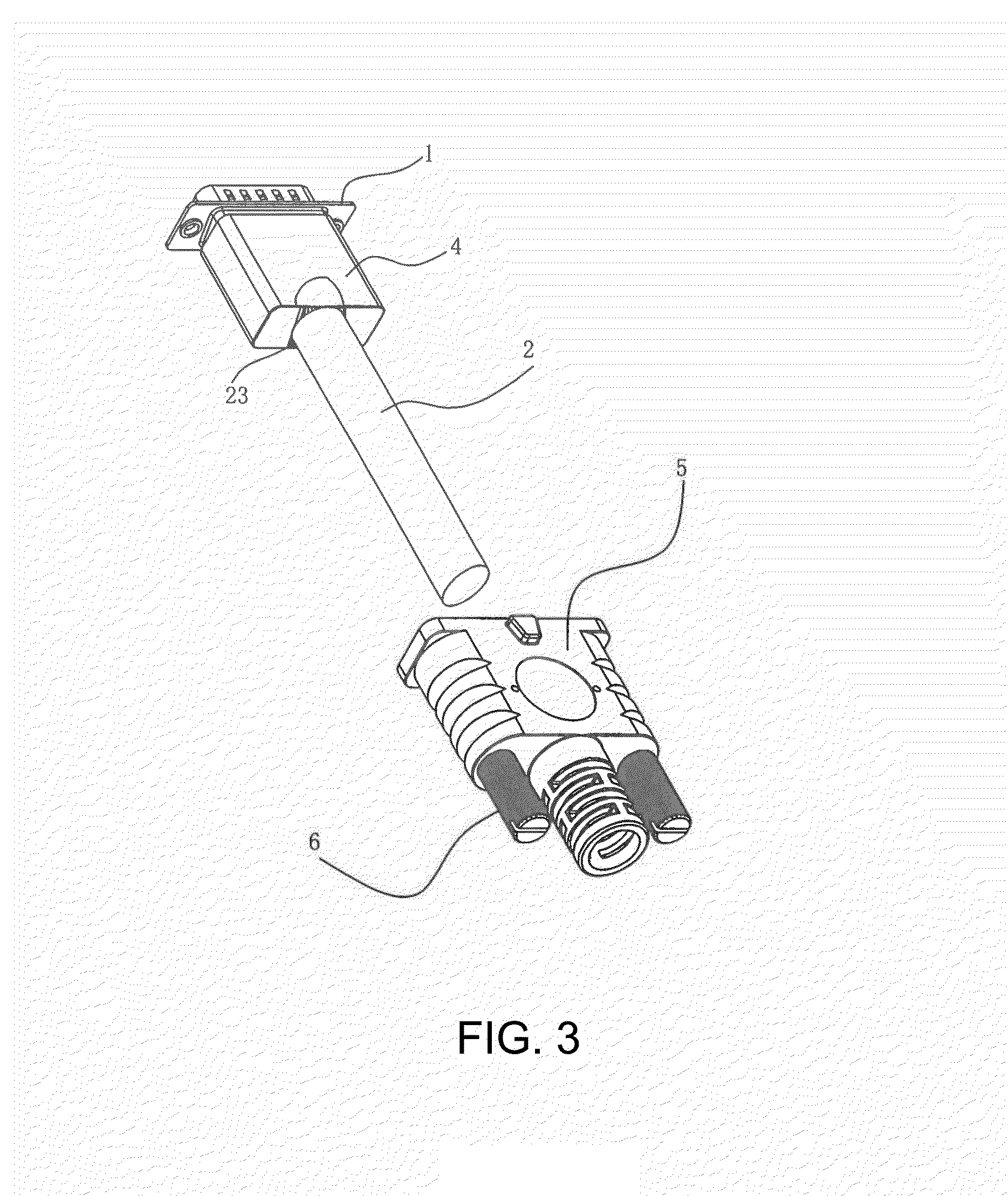
[0019]Referring to FIGS. 1-6, the Present Disclosure provides a cable connector assembly, which co...


PUM


Abstract

A cable connector assembly comprises an electrical connector and a cable connected to a rear side of the electrical connector. The electrical connector comprises an insulative housing and a plurality of conductive terminals fixed thereto. The cable comprises a plurality of wires, a filler among the wires and an insulative covering which covers outer peripheries of the wires and the filler. The wires and the conductive terminals are electrically connected. The cable connector assembly further comprises an inner mold and a casing surrounding an outer periphery of the inner mold. The inner mold is integrally formed at outer peripheries of connections between the conductive terminals and the wires by over-molding. A part of the filler is embedded into the inner mold for stress relief.

Description

REFERENCE TO RELATED APPLICATIONS[0001]The Present Application claims priority to Chinese Utility Model Patent Application No. 201320095906.7, entitled “Cable Connector Assembly,” and filed 1 Mar. 2013, the content of which is fully incorporated in its entirety herein.BACKGROUND OF THE PRESENT DISCLOSURE[0002]The Present Disclosure relates, generally, to a cable connector assembly, and, more particularly, to a cable connector assembly which allows for relief of tensile stress.[0003]Chinese Patent Application No. 200720139591.6, the content of which is fully incorporated herein in its entirety, discloses a cable connector, which comprises an electrical connector and a cable connected to a rear end of the electrical connector. The electrical connector has a plurality of conductive terminals, a shielding shell made from a conductive metal and a clamp device provided at a rear end of the shielding shell. The cable comprises a plurality of wires, a plurality of cable fillers, a metal bra...

Claims


Application Information

Patent Timeline
Patent Type & Authority Applications(United States)
IPC IPC(8): H01R13/58
CPCH01R13/5845H01R13/504H01R13/6591H01R13/65912
Inventor TONG, LINWANG, XIAO-AN
Owner MOLEX INC
Learn More