
Door sill unit and method for an elevator landing door unit

a technology for landing doors and doors, which is applied in the field of door sill units and methods for landing doors in elevators. it can solve the problems that the construction engineer of the building has not been able to finalize the entran

Active Publication Date: 2014-09-11
KONE CORP
View PDF14 Cites 4 Cited by
  • Summary
  • Abstract
  • Description
  • Claims
  • Application Information

AI Technical Summary

Benefits of technology

The fact that the permanent sill and the rail comprising the machinery are installed at a later stage from the elevator shaft is important as it means there is less dust in the air at that time. This can prevent dust from accumulating and causing problems with the operation of the machinery.

Problems solved by technology

The constructor of the building has not been able to finalize the entrance at the landings until the elevator landing door units have been installed.

Method used


Image

  • Door sill unit and method for an elevator landing door unit
  • Door sill unit and method for an elevator landing door unit
  • Door sill unit and method for an elevator landing door unit

Examples


Embodiment Construction

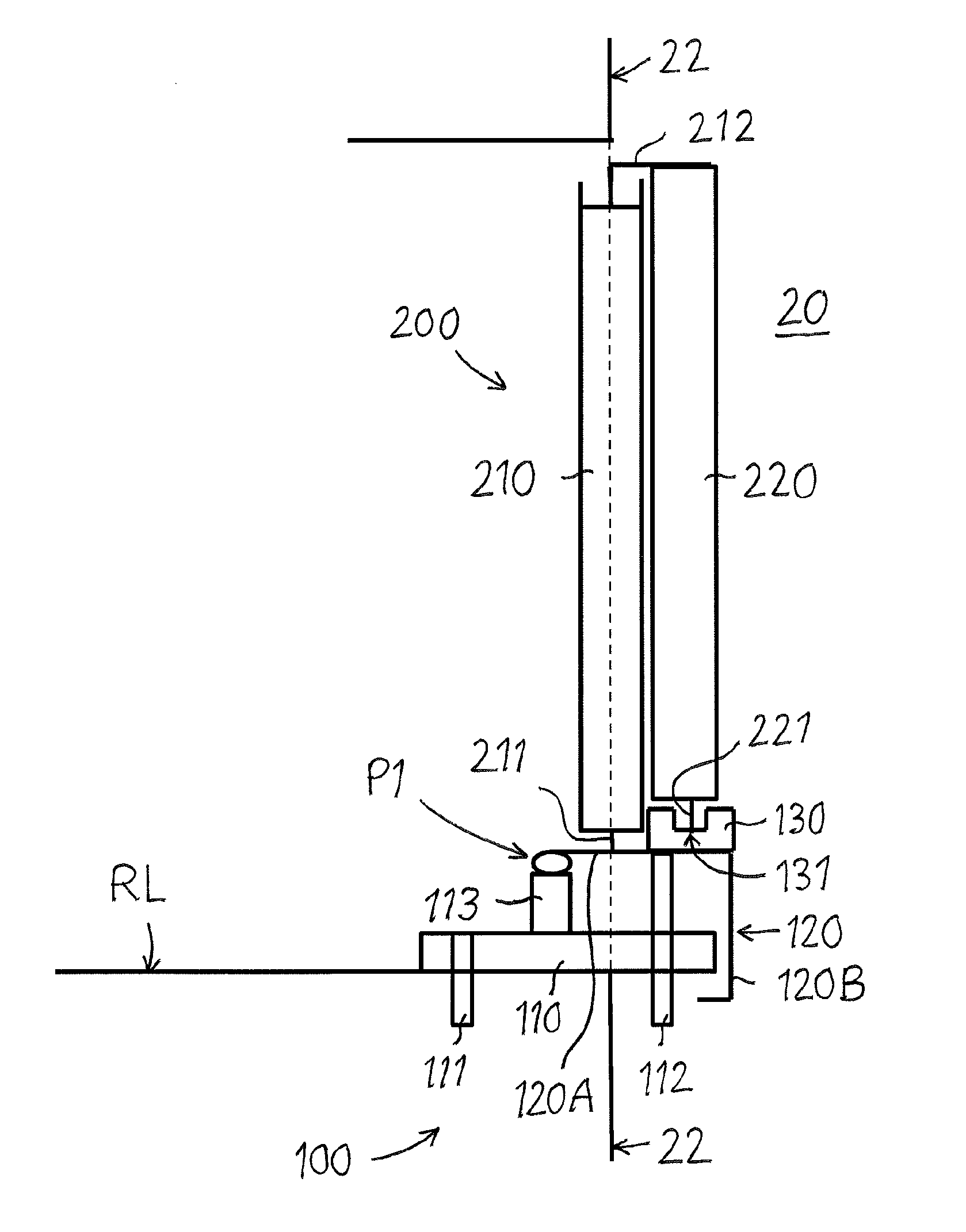
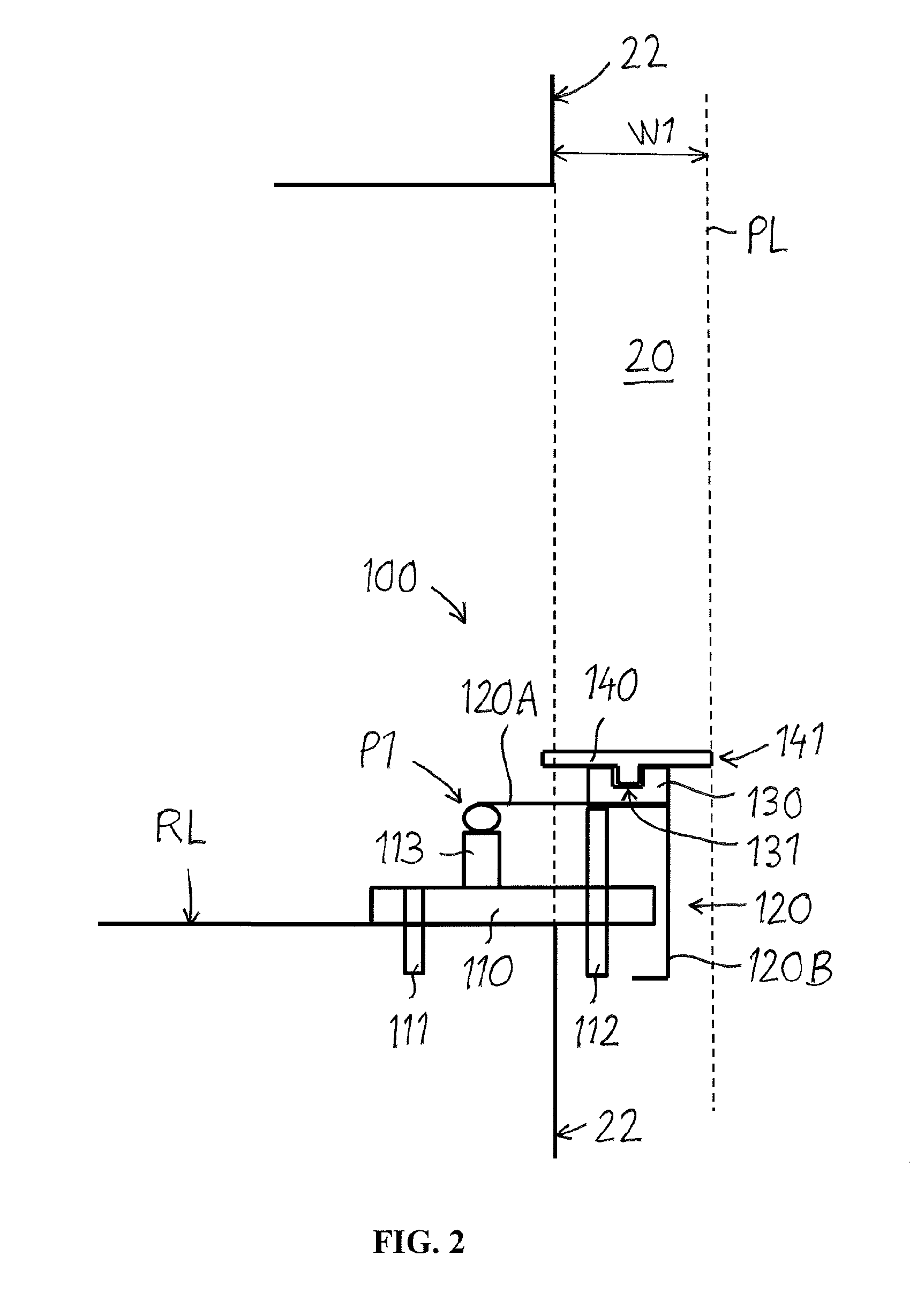
[0024]FIG. 1 shows a vertical cross section of an elevator. The elevator comprises a car 10, an elevator shaft 20, a machine room 30, lifting machinery 40, ropes 41, and a counter weight 42. The lifting machinery 40 moves the car 10 in a first direction S1 upwards and downwards in the vertically extending elevator shaft 20. The car 10 is carried by the ropes 41, which connect the car 10 to the counter weight 42. The car 10 is further supported with guide elements 11 at guide rails 12 extending in the vertical direction in the shaft 20. The figure shows only one guide rail 12, but there can be several guide rails 12 on different sides of the car 10. The guide elements 11 can comprise rolls rolling on the guide rails 12 or glide elements gliding on the guide rails 12 when the car 10 is mowing upwards and downwards. The guide rails 12 are supported with support means 13 at the side wall structures 21 of the elevator shaft 20. The figure shows only two support means 13, but there are se...


PUM

PropertyMeasurementUnit
Heightaaaaaaaaaa

Abstract

The door sill unit includes a bottom support, a support construction extending upwards from the bottom support and a support member being supported by a pivot on the support construction so that the support member can be rotated around the pivot between a first position and a second position.

Description

FIELD OF THE INVENTION[0001]The invention relates to a door sill unit for an elevator landing door unit according to the preamble of claim 1.[0002]The invention also relates to an arrangement in an elevator according to the preamble of claim 8.[0003]The invention also relates to a method for installing an elevator landing door unit according to the preamble of claim 9.[0004]An elevator comprises an elevator car moving in a first direction upwards and downwards in an elevator shaft. The elevator car transports people and / or goods between the landings in a building. The elevator car can thus be stopped at each landing in the building in order for people and or goods to be loaded and / or unloaded to and from the elevator car. There is an elevator landing door unit in each landing in the opening between the landing and the shaft. The elevator landing door unit comprises a frame and at least one door panel. The at least one door panel provides a passage between the landing and the car.BAC...

Claims


Application Information

Patent Timeline
IPC IPC(8): B66B13/30B66B9/00
CPCB66B9/00B66B13/301B66B19/00Y10T29/49623
Inventor ANTTILA, HARRI
Owner KONE CORP
Features
  • Generate Ideas
  • Intellectual Property
  • Life Sciences
  • Materials
  • Tech Scout
  • Unparalleled Data Quality
  • Higher Quality Content
  • 60% Fewer Hallucinations
Learn More